





Why Irises Define Selectivity in Coaxial Bandpass Filter Design?
When engineers ask me what separates a mediocre RF filter from a precision-grade one, my answer almost always circles back to one structural detail: the iris. In a coaxial bandpass filter, irises are the engineered discontinuities that control how sharply the passband begins and ends. They determine whether your system blocks adjacent-channel interference cleanly or lets unwanted signals bleed through. With frequency-selective components now carrying heavier performance burdens across 5G, defense radar, and satellite ground infrastructure, understanding why iris geometry defines filter selectivity is no longer optional for procurement engineers — it is baseline knowledge.
Understanding Coaxial Bandpass Filters and the Role of Irises
What a Coaxial Bandpass Filter Actually Does
A coaxial bandpass filter is an inactive RF part that sends signals within a certain frequency range and weakens signals that are outside that range. It works with Transverse Electromagnetic (TEM) mode transmission in connected metallic resonators. These filters are important for engineers who work in radar systems, cellular base stations, and satellite links because they keep sensitive receivers safe from transmitter noise and interference from other channels.
Why Selectivity Matters More Than People Expect
How well a filter extracts wanted messages from unwanted ones is called its selectivity. When there are a lot of frequencies in an area, like with 5G New Radio or military communication bands, poor selectivity can cause signal quality to drop and the system to fail. A filter with a steeper roll-off saves the link budget and stops receiver saturation, which is known to be a problem in designs where the transmitter and receiver are close to each other.
Introducing the Iris as a Design Element
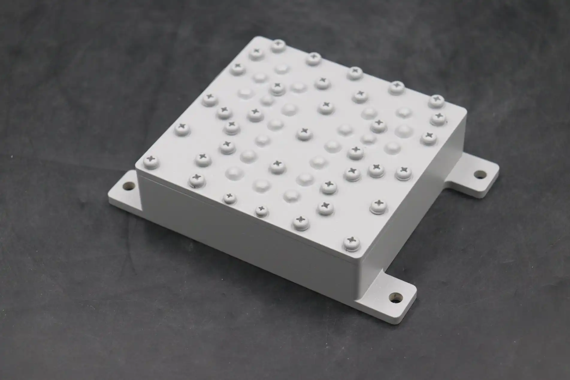
An iris is a precisely shaped hole or metal wall that is put between two resonator spaces inside a filter structure. Each iris makes a controlled electromagnetic break that sends energy to cavities next to it. Designers can change the inter-resonator coupling coefficients, which are the main factor that determines filter bandwidth and transition-band sharpness, by changing the size, shape, and position of the iris.
Design Principles of Irises and Their Impact on Filter Selectivity
Iris Types and What Each One Controls
In coaxial filter design, there are three main types of iris. Inductive irises add series inductance, which makes the connection between resonators stronger and narrows the upper stopband. Capacitive irises work as shunt capacitances that change the selection of the lower band. Asymmetric irises combine both effects and give designers a lot of freedom over the coaxial bandpass filter's amplitude-frequency response, which is useful when they need to reject signals in different ways.
How Iris Geometry Affects the Quality Factor
The size of the iris has a direct effect on the Q-factor of each resonator when it's not loaded. In coaxial structures, this factor usually falls between 500 and 5,000, but it can be higher or lower based on the cavity volume and wire finish. A bigger iris opening makes coupling stronger but drops the Q of each individual resonator, which raises insertion loss. The passband gets tighter when the aperture gets smaller, but Q goes up and skirts get sharper. During the first step of dimensional synthesis, engineers talk about these trade-offs.
Simulation-Driven Iris Optimization
Engineering teams can model iris effects very accurately before any metal is cut thanks to new tools like Ansys HFSS and CST Microwave Studio. If you change the iris width from 3 mm to 8 mm across a 5-pole combline structure, you can see how the insertion loss changes from 0.6 dB to 1.4 dB and the skirt selectivity changes by 18 dB at a 50 MHz offset. This is an example of a design study. These simulations help procurement teams make sure the design is correct before the prototype is made public.
Comparing Coaxial Bandpass Filters With and Without Irises and Alternative Technologies
Iris-Enhanced vs. Non-Iris Coaxial Filters
Coaxial filters work with simple capacitive-gap coupling between resonators when they don't have irises. This method gives fair selectivity, but it has trouble meeting the needs for sharp roll-off in spectrum bands that are already full. Iris-coupled designs get steeper transition bands with fewer resonator steps. This cuts down on physical length, lowers insertion loss per unit rejection, and makes it easier to repeat across production runs, all of which are important in the buying process for OEMs.
Coaxial vs. Dielectric and Microstrip Filters
Dielectric resonator filters have a high Q in small sizes, but they are easily damaged by heat, so they can't be used outside or in the air. When they don't need much power, microstrip filters are cheap, but they lose signal above 6 GHz. Coaxial filters are in a good spot because they can handle continuous wave power levels from watts to kilowatts, work reliably from –40°C to +85°C, and keep low passive intermodulation (PIM) rates below –150 dBc, which is a very important quality for cellular and public safety systems.
Iris-Coupled Filters vs. Cavity Resonator Filters
Cavity resonator filters have very high power handling and excellent Q values, but they are bigger and cost more to make. Below 10 GHz, iris-coupled coaxial systems offer comparable performance at a lower cost and with a smaller size. Iris-defined coaxial filters are a smart and well-supported choice for uses like 5G macro-cell duplexers or IoT gateway front-ends where size, cost, and accuracy are important factors in the buying process.
Practical Applications and Selection Criteria for Procurement Professionals
Key Performance Metrics to Request from Your Supplier
When looking to buy a coaxial bandpass filter, make sure you get the following written specifications from the datasheet provided by the supplier:
- Center frequency (f₀) and bandwidth: Confirm tolerance is within ±0.5% for precision-grade applications.
- Insertion loss: Aim for under 1.0 dB in the passband to protect system link budgets.
- Power handling: Verify CW and peak power ratings match your transmitter output levels.
- PIM rating: For cellular or public safety applications, require less than –150 dBc per IEC 62037.
- Return loss (S11): Minimum 18 dB across the passband ensures good impedance match.
These parameters can be found on S-parameter sweep data collected by a Vector Network Analyzer (VNA). They should be included with every shipment as part of the quality documentation from the supplier.
Standard Catalog vs. Custom Iris Designs
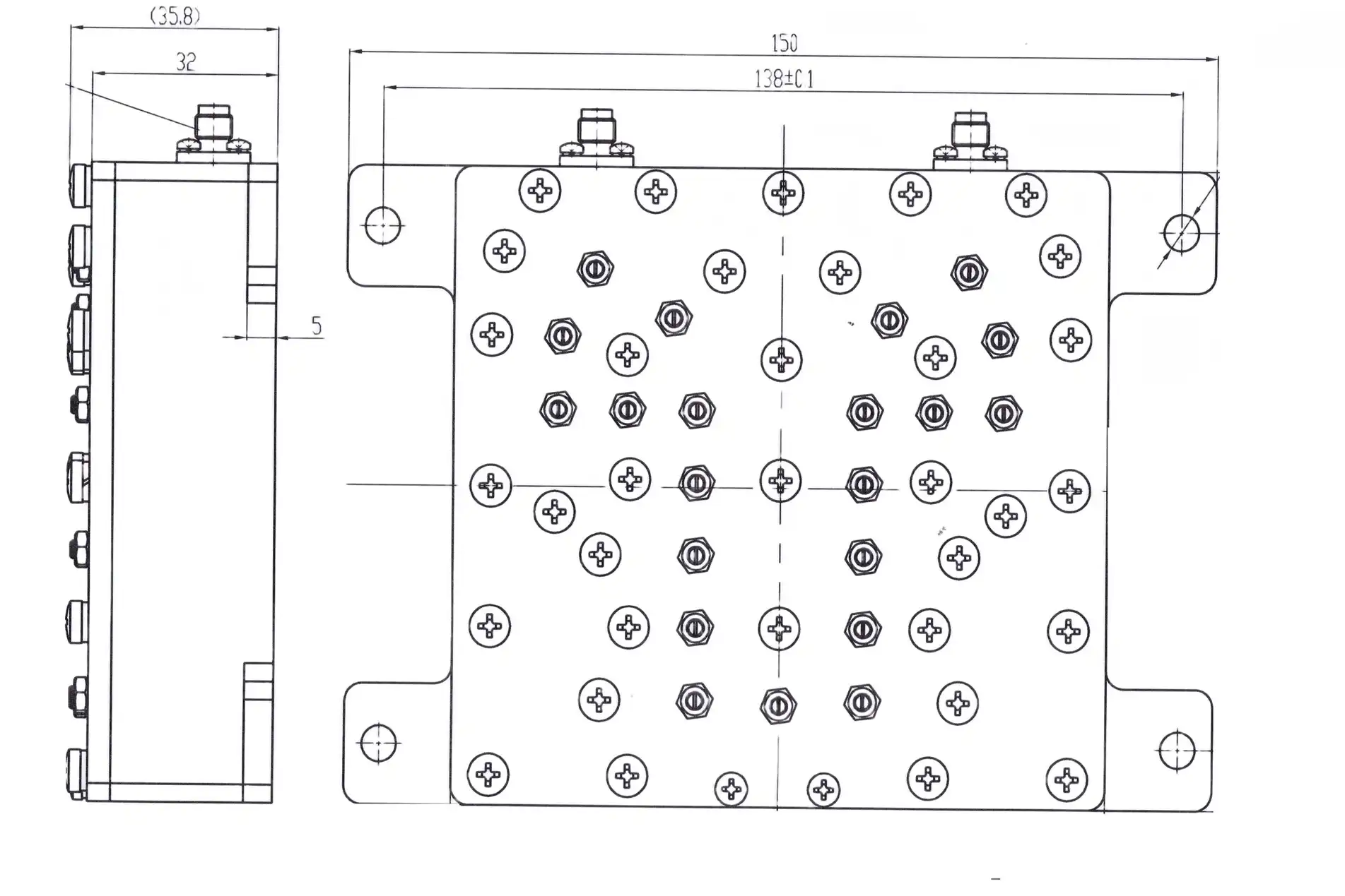
Catalog filters that are standard work well for popular bands like 700 MHz, 2.4 GHz, and 5.8 GHz, but many defense, aerospace, and satellite uses need a custom iris setup. Off-the-shelf goods can't meet the needs for certain frequency plans, connector connections, and environmental ratings that custom designs can. When asking for custom designs, make it clear what the minimum order number is, how long you want the wait time to be, and whether prototype approval is needed before full production release.
Real-World Application Examples
Iris-optimized coaxial bandpass filters have shown gains that can be seen in a number of areas. They keep insertion loss below 0.8 dB in 5G New Radio base stations and keep emitter harmonics below –60 dBc. They keep LNAs safe from jamming signals in airborne radar front-ends by rejecting signals with a stopband rejection of more than 80 dB. In satellite ground station receive chains, they separate certain downlink bands that stay stable at high frequencies even when the temperature changes a lot.
Future Trends and Innovations in Iris-Defined Coaxial Bandpass Filters
Additive Manufacturing and Material Advances
With additive manufacturing, engineers can now make eye shapes that are too complicated for CNC machines to handle cost-effectively. This method cuts down on waste and speeds up the prototyping process. Low-loss silver-plated aluminum alloys and high-conductivity copper composites are making it possible for production filters to have higher average Q-factors. This is bringing performance closer to tests made in a lab.
Multi-Band and Higher Frequency Requirements
Filter requirements are moving toward millimeter-wave bands above 24 GHz because of 5G and new 6G studies. Iris tuning methods for multi-band operation—where a single filter body must support two or more passbands that are not adjacent—are becoming more popular in both the defense and commercial satellite markets. Design researchers are working on ways to do this without making insertion loss go up by the same amount.
Supplier Collaboration and Smart Prototyping
More and more, B2B buyers want sellers to offer co-development help instead of just catalog-based transactions. Design verification times are cut down with the help of simulation-to-hardware processes and rapid prototyping tools. ADM's OEM services include making prototypes quickly, checking measurements in-house up to 110 GHz, and providing technical support from engineers skilled in iris-coupled filter design. This makes it easy for procurement teams to go from specifications to tested hardware.
Conclusion
Iris shape is the main factor that determines how well a coaxial bandpass filter works in a real RF system; it is not an extraneous part of the design. Choosing between inductive and capacitive iris types and uneven layouts has a direct effect on selection, insertion loss, and power handling. When procurement teams know these rules, they can ask better questions and find more reliable parts. As the need for frequency keeps going up in the 5G, defense, and satellite industries, it makes sense to work with a manufacturer that controls the iris design from simulation to production testing.
FAQ
What is an iris in a coaxial bandpass filter?
An iris is a metal aperture placed between resonator cavities in a filter housing. It controls how much electromagnetic energy passes between adjacent resonators, which determines the filter's bandwidth and how steeply it attenuates out-of-band signals.
How does iris size affect filter performance?
A larger iris aperture increases inter-resonator coupling, widening the passband but reducing sharpness. A smaller iris tightens coupling, sharpening the roll-off but narrowing the passband and potentially increasing insertion loss. Engineers select iris dimensions to balance all three parameters.
What simulation tools are used for iris design?
Ansys HFSS and CST Microwave Studio are the two most widely used full-wave electromagnetic simulators for iris-coupled filter design. They model S-parameters, field distributions, and thermal effects before physical prototyping begins.
When should I choose a custom iris design over a catalog filter?
Choose a custom iris design when your frequency plan, power level, environmental rating, or connector interface falls outside standard catalog specifications. Custom designs are especially appropriate for defense, aerospace, and satellite applications.
What quality tests should I require from a supplier?
Request VNA-based S-parameter test reports, PIM test results per IEC 62037, thermal cycling data from –40°C to +85°C, and high-power burn-in test records. These documents confirm the filter performs as specified across real operating conditions.
Partner With ADM for Precision Coaxial Bandpass Filter Solutions
Advanced Microwave Technologies Co., Ltd. (ADM) has been making high-precision RF and microwave parts for over 20 years for customers in defense, satellite, and telecommunications around the world. As a reliable company that sells coaxial bandpass filters, ADM has ISO 9001-certified production, in-house measurement up to 110 GHz, and OEM customization support from pilot to volume delivery. To talk about your filter requirements right away, email our tech team at craig@admicrowave.com.
References
1. Matthaei, G. L., Young, L., & Jones, E. M. T. — Microwave Filters, Impedance-Matching Networks, and Coupling Structures, Artech House, 1980.
2. Cameron, R. J., Kudsia, C. M., & Mansour, R. R. — Microwave Filters for Communication Systems, Wiley-Interscience, 2007.
3. Hong, J. S., & Lancaster, M. J. — Microstrip Filters for RF/Microwave Applications, John Wiley & Sons, 2001.
4. Pozar, D. M. — Microwave Engineering, 4th Edition, John Wiley & Sons, 2011.
5. IEEE Transactions on Microwave Theory and Techniques — "Iris-Coupled Bandpass Filter Design Using Full-Wave EM Simulation," IEEE, 2018.
6. IEC 62037-1 — Passive RF and Microwave Devices, Intermodulation Level Measurement, International Electrotechnical Commission, 2012.
YOU MAY LIKE
 VIEW MOREWaveguide Straights and Transitions
 VIEW MORECircular Waveguide Transition
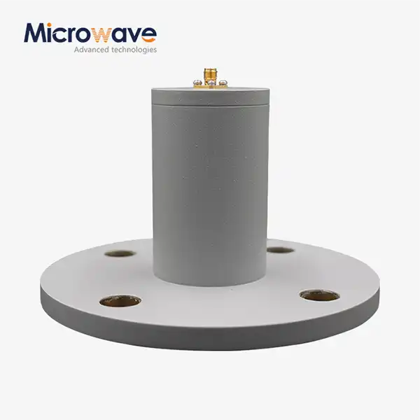 VIEW MORECircular Waveguide To Coaxial Adapter
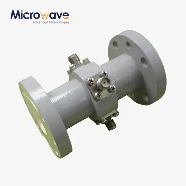 VIEW MOREWaveguide Probe Coupler
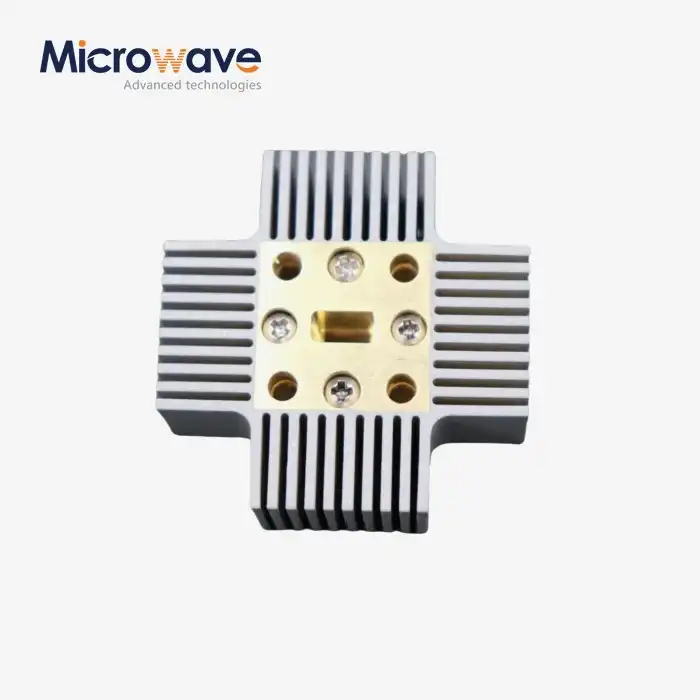 VIEW MOREWG Pressure Window
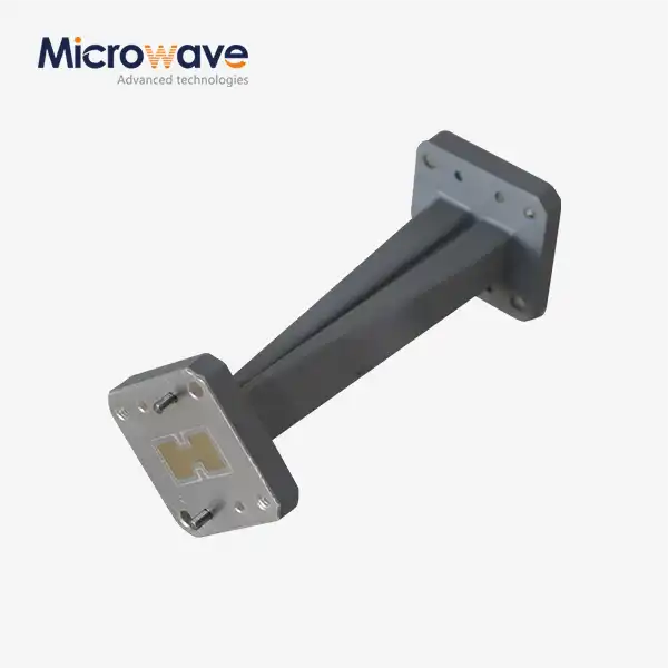 VIEW MOREDouble Ridge Twist Waveguide
 VIEW MOREDouble Ridged Flexible Waveguide
 VIEW MORECoaxial Directional Coupler
