





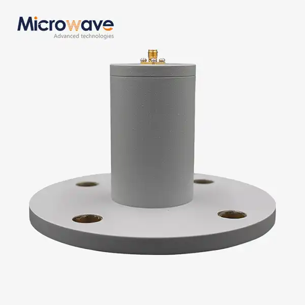
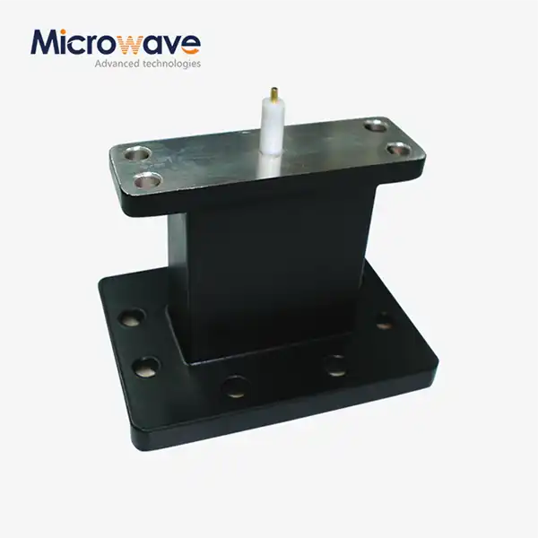
Circular Waveguide To Coaxial Adapter
Circular Waveguide To Coaxial Adapter for SATCOM & Radar Systems — Maximum VSWR 1.15:1
The Circular Waveguide To Coaxial Adapter from Advanced Microwave Technologies Co., Ltd. (ADM) converts the dominant TE11 mode in circular waveguide feeds to the TEM mode used in coaxial lines. Key electrical performance includes a maximum VSWR of 1.15:1 and insertion loss below 0.3 dB. Frequency coverage is configured to customer-specified bands, including X-Band (8–12 GHz) and Ku-Band (12–18 GHz). Body materials are oxygen-free high-conductivity copper or aluminum, finished with silver or gold plating.
What Is a Circular Waveguide To Coaxial Adapter?
This adapter is a passive electromechanical component that transitions electromagnetic energy between a circular waveguide transmission line and a coaxial cable interface. Its primary function is mode conversion — changing the TE11 mode in the circular waveguide to the Transverse Electromagnetic (TEM) mode required by coaxial lines.
Compared to rectangular waveguide adapters, which handle the linearly symmetric TE10 mode, the TE11 mode in a circular waveguide has rotational degrees of freedom. This makes the probe geometry and polarization orientation more critical to specify correctly.
In system-level terms, this adapter connects circular waveguide antenna feeds — such as conical horns — to coaxial test equipment, LNBs, or BUCs. It addresses impedance mismatch, signal reflection, and polarization degradation at the waveguide-to-coaxial transition point.


Key Electrical & Physical Specifications
Parameter | Specification |
Frequency Range | Customized (e.g., X-Band 8–12 GHz, Ku-Band 12–18 GHz) |
VSWR | ≤ 1.15:1 (high-precision grade); industry standard < 1.25:1 |
Insertion Loss | < 0.2 dB – 0.3 dB (frequency and plating dependent) |
Mode | TE11 (circular waveguide) → TEM (coaxial) |
Mode Purity | TE11 dominant; TM01 and higher-order modes suppressed |
Body Material | Oxygen-free high-conductivity copper or aluminum |
Plating | Silver or Gold; Nickel-Gold available for marine/high-humidity use |
Coaxial Interfaces | N-type, SMA, 2.92 mm, 2.4 mm |
Flange Type | UG series standard or custom metric circular flanges |
Flange Alignment | Indexing holes for mechanical alignment |
Note: The internal launching probe is tuned to quarter-wavelength dimensions of the target operating frequency. Operating outside the specified band causes impedance mismatch and elevated signal reflection.
Material & Construction Details
Depending on how much power the application needs and how light it needs to be, the Circular Waveguide To Coaxial Adapter body is made from either oxygen-free high-conductivity (OFHC) copper or aluminium.
Surface treatment changes both how well electricity works and how long it lasts in harsh environments. Skin-effect losses are lower with silver plating, which is the standard choice for most communication and lab uses. Nickel-gold plating or silver with a tarnish-resistant finish makes things more resistant to corrosion in marine or high-humidity settings without losing a lot of conductivity.
The frequency range of the chosen connector type is matched to the coaxial interface. N-type connectors can handle up to 18 GHz, and 2.92 mm connections can handle up to 40 GHz. As part of the setup process, you have to choose the right type of connector for your operating band.
Polarization Capability
Linear polarisation can be used with a standard single-probe adapter. The polarisation vector is set by the orientation of the coaxial launch pin. By default, the output is linearly polarised.
This device is usually used with a septum polariser or phase shifter in systems that need circular polarisation. In order to receive both vertical (V) and horizontal (H) signals at the same time, you need an Orthomode Transducer (OMT), which works as a dual-port waveguide transition.
By stating the polarisation need during the ordering process, you can be sure that the probe orientation and any paired components are set up properly for your feed chain.
Application Scenarios
SATCOM Feed Chains
This device moves the downlink signal from the circular waveguide horn to the LNB downconverter in a satellite ground station feed chain. Adding loss at this stage changes the system noise number and the Signal-to-Noise Ratio (SNR) of weak satellite signals in a direct way. This is why the sub-0.3 dB specification is important in this case.
Meteorological & Defense Radar
It is these adapters that link the antenna structure to the spherical waveguide outputs of magnetrons or solid-state amplifiers. In radar settings, pulse accuracy during weather mapping or target tracking is affected by phase stability when temperature changes and mechanical vibrations happen.
Precision Antenna Measurement
These adapters let circular standard gain horns connect to Vector Network Analysers (VNAs) in rooms with no echo. The adapter is used as a calibrated point of reference to describe the far-field antenna design and measure the gain. ADM has a 24 m Microwave Darkroom that can switch between near-field and far-field frequencies from 0.5 GHz to 110 GHz. It uses this type of adapter in its own measurement processes.
Power Handling Considerations
The side that is coaxial is what limits the power in this assembly. The coaxial connector geometry and dielectric bead will reach their thermal or breakdown limits at lower power levels, while circular waveguide sections can handle much higher power levels.
Air-dielectric connectors and aluminium bodies are the right combination for high-power CW (Continuous Wave) uses. Before deployment, the power rating of the chosen coaxial connector should be compared to the amount of power that will be sent.
Customization & Ordering Information
ADM can set up Circular Waveguide To Coaxial Adapters with different frequency bands, flange types, connector interfaces, body materials, and plating choices. The operating frequency has to be chosen at the time of ordering because the internal probe is tuned to quarter-wavelength dimensions for a certain band. The probe geometry can't be switched between bands.
You can get custom metric flanges, non-standard coaxial interfaces, and plating made especially for harsh environments. Craig@admicrowave.com to get in touch with the ADM engineering team and make sure you have the right configuration for your system.
Quality Assurance & Testing Capability
ADM has a special microwave darkroom that is 24 meters long and has an antenna plane near and far field measuring recombination chamber. This makes it easy to switch between near-field and far-field measurement modes from 0.5 GHz to 110 GHz.
Before it is shipped, VSWR and insertion loss tests are done on every adapter. A "Thru" or "Short-Short" calibration based on a VNA is suggested for incoming inspection. To properly de-embed the adapter and measure return loss and insertion loss, you need a Waveguide Calibration Kit in either TRL or SSL format because the waveguide port is not coaxial.
FAQ
Q: How does a product handle polarization compared to a rectangular waveguide adapter?
A: Rectangular adapters are linearly polarized by the fixed geometry of the rectangular cross-section. A circular adapter supports the TE11 mode, which has rotational degrees of freedom. The coaxial launch pin sets a linear polarization vector by default. For circular polarization, the adapter is paired with a septum polarizer or phase shifter.
Q: Why must the operating frequency band be specified when ordering?
A: The internal launching probe is machined to quarter-wavelength dimensions for a specific frequency. Using the adapter outside its designed band results in impedance mismatch, elevated VSWR, and increased signal reflection. Frequency band must be confirmed before production.
Q: What limits the power handling of this adapter?
A: Power handling is constrained by the coaxial connector interface and its dielectric bead, not the waveguide section. SMA connectors carry lower power ratings than N-type connectors. For high-power CW applications, air-dielectric connectors and aluminum bodies are the appropriate choice.
Q: Can this adapter connect two different circular waveguide sizes?
A: No. This device transitions from circular waveguide to coaxial line. Transitioning between different circular waveguide cross-sections requires a Circular Waveguide Taper or a dedicated waveguide-to-waveguide transition.
Q: What plating is recommended for marine or high-humidity environments?
A: Nickel-Gold plating or silver with a tarnish-resistant finish is recommended for marine or high-humidity deployments. This combination maintains adequate conductivity while providing improved corrosion resistance.
Q: How should performance be verified after receiving the adapter?
A: Connect the adapter to a VNA and perform a "Thru" or "Short-Short" calibration. Use a Waveguide Calibration Kit in TRL or SSL format to de-embed the waveguide port and obtain accurate return loss and insertion loss measurements.
Contact Us
For technical inquiries or custom quotes on a Circular Waveguide To Coaxial Adapter, contact ADM at craig@admicrowave.com.
YOU MAY LIKE
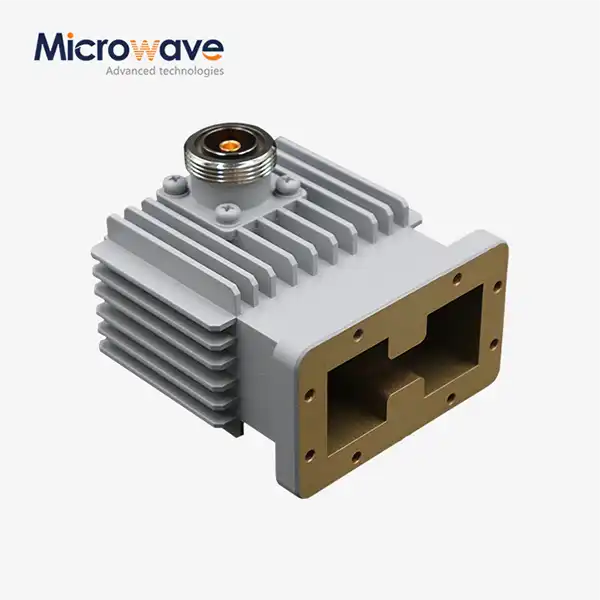 VIEW MOREHigh Power Waveguide to Coaxial Adapter
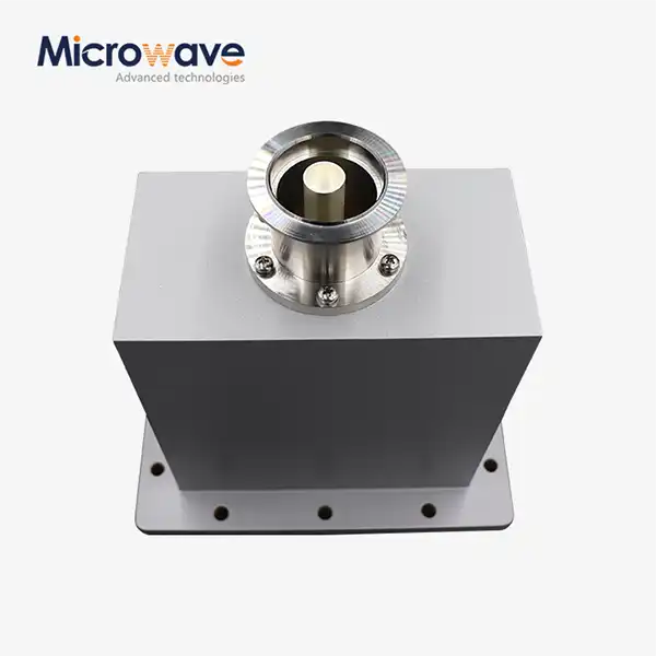 VIEW MOREEnd Launch Waveguide to Coaxial Adapter
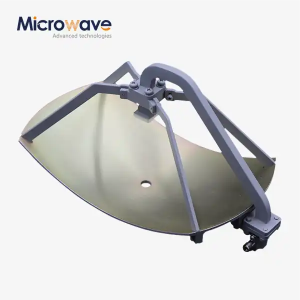 VIEW MOREParabolic Antenna
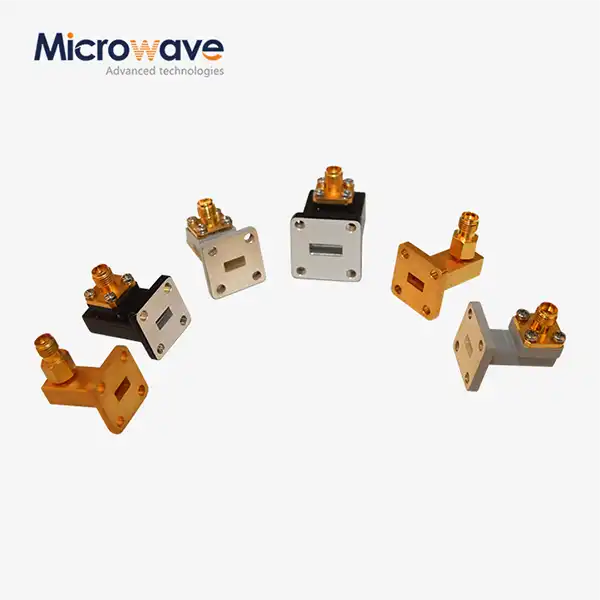 VIEW MORERight Angle Waveguide To Coaxial Adapter
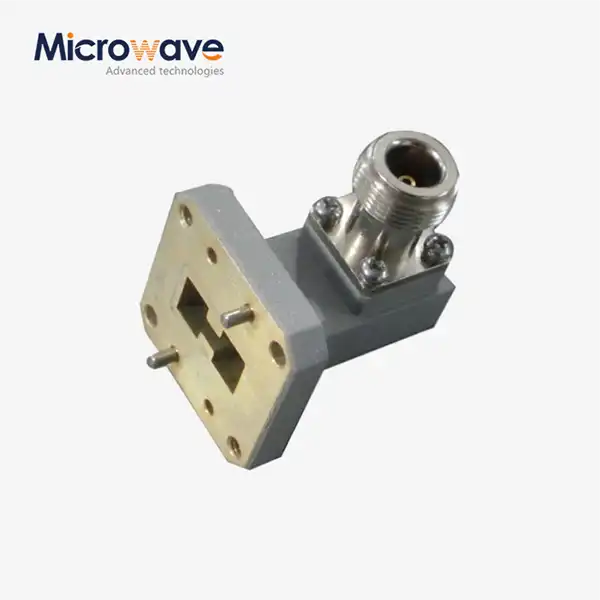 VIEW MORERight Angle Double Ridged WG To Coaxial Adapter
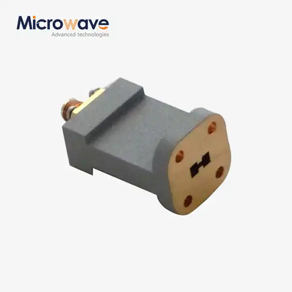 VIEW MOREEnd Launch Double Ridged WG To Coaxial Adapter
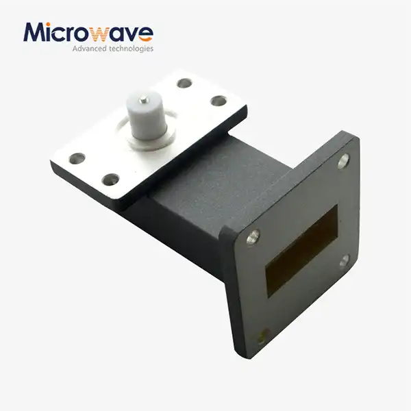 VIEW MORERight Angle Waveguide to Microstrip Adapter
 VIEW MOREEnd Launch Waveguide to Microstrip Adapter
