Waveguide Probe Coupler
Waveguide Probe Coupler — Fixed & Adjustable Coaxial-to-Waveguide Transitions
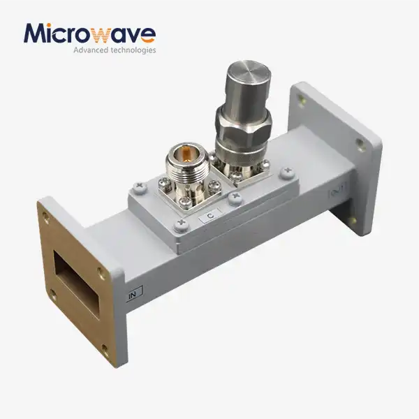
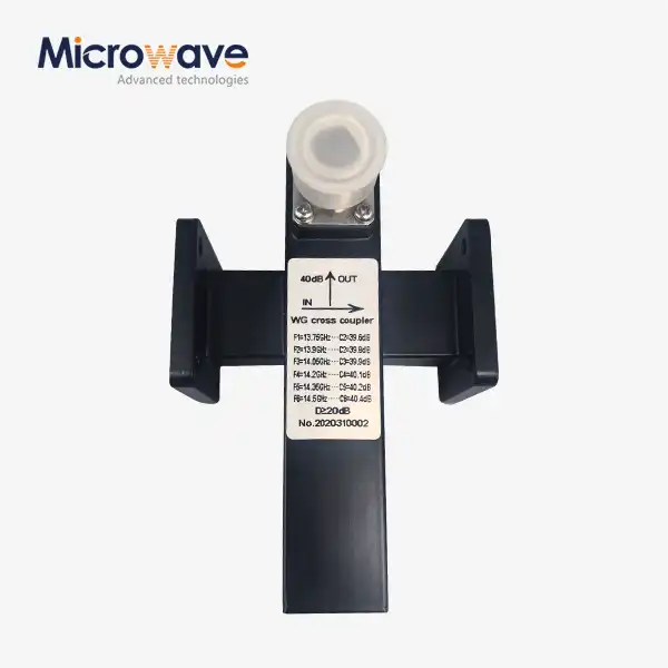
Waveguide Probe Couplers from Advanced Microwave Technologies (ADM) can be made in both fixed and adjustable forms. By connecting energy through an internal metallic monopole probe, these passive parts connect 50-ohm coaxial transmission lines to square or round waveguides. ADM's products work with bands from 0.5 GHz to 110 GHz and are used for things like millimeter-wave test systems, satellite communication, and radar feed networks.
What Is a Waveguide Probe Coupler?
A product is a passive RF part that links waveguide and coaxial transmission devices. The characteristic impedances of the coaxial line and the hollow waveguide are not the same. This mismatch needs to be fixed before energy can move easily between them.
A metallic monopole probe is put through the wide wall of a rectangular waveguide and placed about λ/4 away from the back wall of a short-circuit. This placement makes constructive interference, which pushes electromagnetic energy forward and stops reflected waves, which makes the dominant TE10 mode more active.
The probe takes voltage and current data from solid-state electronics and turns them into electromagnetic fields that can travel. This makes it a useful part for antenna feeds, radar networks, and RF distribution systems.
Fixed vs. Adjustable Probe Coupler
To meet the needs of different systems, ADM makes goods that are both fixed and adjustable (tunable).
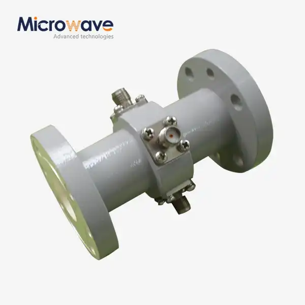
Fixed probe couplers are set to a backshort position at the factory that is best for broad performance across a standard waveguide band. They work well in situations where a constant coaxial-to-waveguide interface is needed without having to change the field.
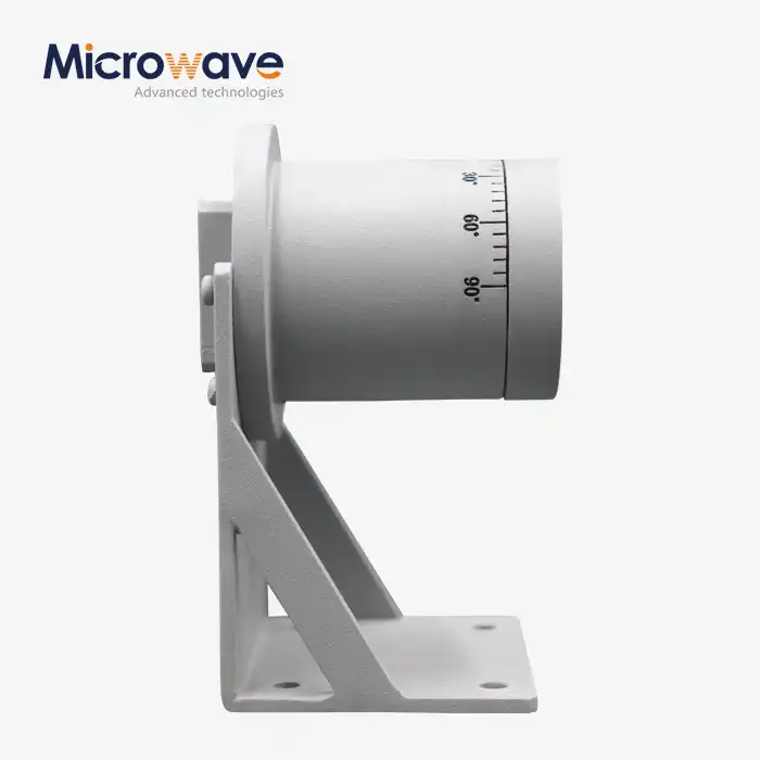
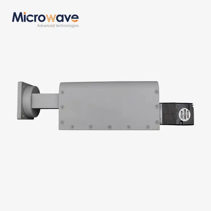
A backshort (sliding plunger) can be moved on adjustable probe couplers. The backshort can be moved mechanically by engineers to set the standing wave pattern for a certain narrow frequency. It is helpful to have this kind of flexibility in resonance cavities, lab test setups, and narrowband radar feeds.
Standard probe designs cover around 20 to 30 percent of the waveguide's bandwidth. ADM can talk about advanced systems that use ridge loading or multi-stage impedance matching to get full-band coverage.

Key Technical Specifications
Parameter | Details |
Coupler Type | Fixed Probe Coupler / Adjustable Probe Coupler |
Mode Supported | Dominant TE10 mode (rectangular waveguide) |
Probe Position | λ/4 from short-circuit back wall |
Connector Interface | SMA, N-Type, 7/16 DIN (application-dependent) |
Frequency Coverage | Customizable, up to 110 GHz |
Waveguide Type | Rectangular or Circular |
Material / Plating | Silver plating standard; optional gold flash for corrosion resistance |
Backshort Type | Fixed or Sliding (tunable) |
Application Environment | Aerospace, SATCOM, radar, lab testing |
Performance and Design Considerations
In waveguide probe couplers, probe depth and backshort distance are the two main factors that determine bandwidth and impedance matching. It's called reactive mismatch if the backshort position moves because of thermal expansion or bad assembly. This lowers both VSWR and usable bandwidth.
Most of the time, the power handling limit is set by the coaxial connector link. N-Type or 7/16 DIN connectors can handle higher continuous wave (CW) power before they hit their thermal or breakdown limits. SMA connectors work best with lower power levels.
When used in a vacuum or space, couplers must be marked as either vented or tightly sealed. As the air pressure drops, air pockets that don't have vents can cause outgassing or corona discharge, which is a very important thing to think about when designing satellite payloads and aerospace.
Application Scenarios
Radar Feed Networks (X/Ku-Band): These couplers move data from high-power amplifiers to antenna arrays in weather and fire radar systems that need to handle a lot of peak power and be mechanically stable.
SATCOM Satellite LNB Design: In ground station Low Noise Block (LNB) downconverters, the coupler moves Ku- or Ka-band signals from the feed horn to electronics on a PCB while keeping the noise figure as low as possible.
5G mmWave Test & Measurement: In the lab, waveguide probe couplers work as precise adapters for Vector Network Analysers (VNAs), which lets S-parameter characterisation of waveguide filters, antennas, and other parts that are linked.
ADM Engineering and Testing Capability
ADM runs a 24-meter microwave darkroom with an antenna plane near and far field measuring recombination chamber that can handle tests in both near and far fields from 0.5 GHz to 110 GHz. This area goes from the usual communication bands to millimeter-wave frequencies.
ADM has offices in Chengdu, Beijing, Tianjin, and Shijiazhuang, as well as a research and development (R&D) lab. Direct enquiries can be used to look into custom engineering requests, such as changing the shape of the probe, the connector, or the surroundings to make it harder.
FAQ
Q: What is the difference between a product that is fixed and one that can be tweaked?
A: A fixed coupler is set to a backshort setting that works best for broadband use when it is first made. An adjustable coupler has a backshort plunger that can be moved. This lets the standing wave pattern be set to a narrow frequency, which is good for testing in the lab or working on resonance cavities.
Q: What limits how much power a probe connection can handle?
A: The coaxial connector interface and the dielectric gap around the probe are the main things that limit the signal. The power threshold goes up a lot if you choose a bigger connector format like N-Type or 7/16 DIN instead of SMA.
Q: Does a probe coupler work with the whole waveguide frequency range?
A: Standard designs cover around 20 to 30 percent of the waveguide band. For full-band coverage, you need advanced probe shapes like stepped or ridge-loaded designs, along with impedance matching that happens over multiple stages.
Q: What should be done to keep the connector interface in good shape?
A: To get rid of dust, use clean, dry air. If you need to, clean the connector pin and flange face with isopropyl alcohol on a lint-free swab. To keep absorption and resistance changes from happening, don't touch any internal dielectric material.
Contact Us
Send your frequency range, waveguide size, and connector requirements for waveguide probe couplers to craig@admicrowave.com and an ADM engineer will follow up directly.