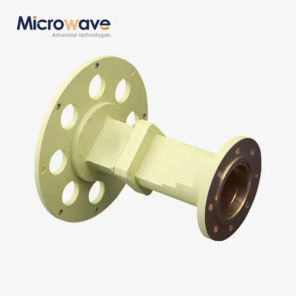
Circular Waveguide Transition
Circular Waveguide Transition for Microwave & Satellite Systems
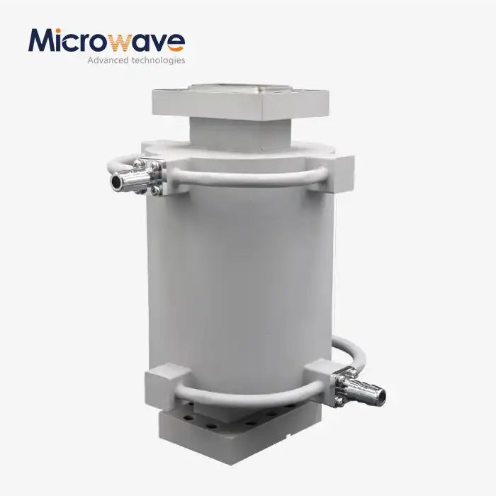
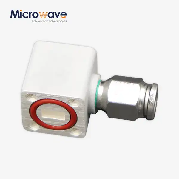
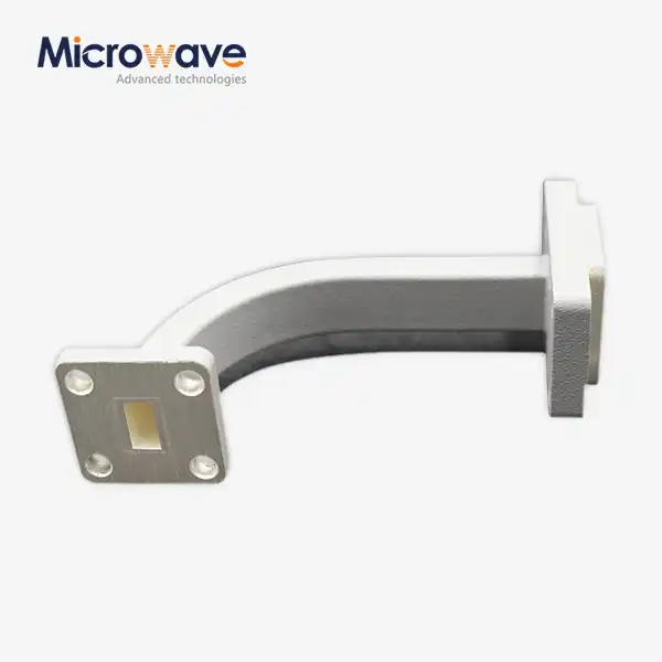
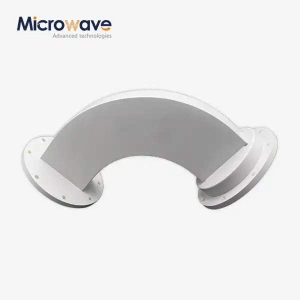
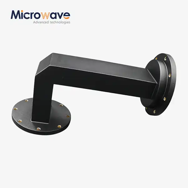
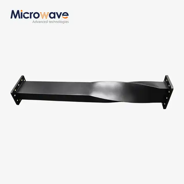
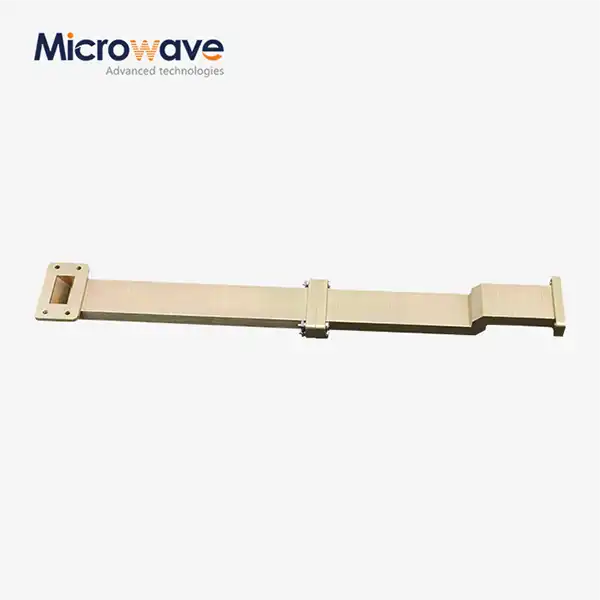
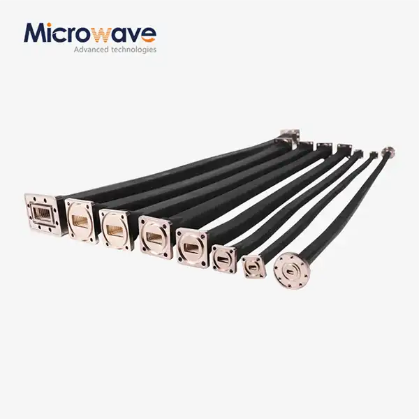
Advanced Microwave Technologies Co., Ltd. (ADM) designs and manufactures Circular Waveguide Transition components that convert signal transmission between rectangular and circular waveguides, or between different circular waveguide sizes. Built from OFHC Copper, Aluminum, or Brass with silver or gold surface plating, these passive RF components are specified at VSWR below 1.10:1 and insertion loss under 0.1 dB, covering frequency bands from X-Band through Ka-Band and beyond, with test capability spanning 0.5 GHz to 110 GHz.
What Is a Circular Waveguide Transition?
A product is a passive microwave component that converts electromagnetic energy between rectangular waveguide modes (TE10) and circular waveguide modes (TE11), or between different circular waveguide sizes. It transforms field modes while maintaining impedance matching across the operating bandwidth.
Rectangular waveguides are standard for integrating components such as filters and isolators. Circular waveguides are preferred for long-distance transmission and antenna feeds because of their rotational symmetry and lower attenuation. This transition bridges both geometries without compromising signal integrity or phase linearity.


Key Electrical & Mechanical Properties
These transitions are defined by controlled electrical performance and mechanical precision. Units are manufactured to meet EIA and MIL-DTL-85 specifications for flange flatness and dimensional tolerances.
Parameter | Specification |
VSWR | < 1.10:1 over operating bandwidth |
Insertion Loss | < 0.1 dB |
Cross-Polarization Discrimination (XPD) | > 30 dB |
Dominant Circular Mode | TE11 |
Suppressed Spurious Modes | TM01 and higher-order modes |
Operating Frequency Bands | X-Band, Ku-Band, Ka-Band (custom available) |
Material Options | OFHC Copper, Aluminum, Brass |
Surface Finish | Silver plating or Gold plating |
Flange Standards | EIA CPR, UG cover/choke, UG-series circular, custom |
Taper Design | Adiabatic (gradual) or stepped-impedance |
Mode Purity: Why It Matters
Mode purity is a very important part of how well any circular waveguide transition works. When mode purity is low, signal energy changes into unwanted spurious modes that move at different speeds. This causes signal distortion, phase errors, and less Cross-Polarization Discrimination (XPD), which directly impacts the integrity of data in dual-polarization systems.
ADM's transitions use adiabatic tapers that are precisely machined and span several wavelengths. This slow change in shape reduces abrupt breaks as much as possible and creates a clean TE11 output with an XPD level above 30 dB. Stepped-impedance designs are available for setups that don't have a lot of room. These designs are optimised for specific frequency targets while keeping the total footprint small.
Application Scenarios
Satellite Communication (SATCOM) Feed Systems
The shift links square diplexers to round antenna feed horns in satellite ground stations and payloads in space. Its rotational symmetry allows both linear and circular polarisation, which means that a single antenna can send and receive on different polarisations at the same time over Ku-Band and Ka-Band commercial satellite links.
High-Power Radar & Weather Monitoring
These transitions connect high-power magnetrons or klystrons with rectangular outputs to rotating joints and circular antenna feeds. They are used in military and weather radar systems. The transition has to be able to handle high power in the kilowatt range, handle thermal cycling, and keep insertion loss low.
5G/6G mmWave Test & Measurement
In RF labs and places that make semiconductors, transitions connect regular rectangular waveguide test modules, like VNA extenders, to circular probe stations or horn antennas. To keep measurement errors to a minimum in the E-band (60–90 GHz) and W-band (75–110 GHz), it is important to use precise machining and check that the flanges are perfectly centred.
Materials, Surface Finish & High-Power Handling
At millimeter-wave frequencies, the choice of material has a direct effect on performance. OFHC Copper has the best transmission for low skin-effect losses. Aluminium is a lighter option for aerospace platforms that need to be light. Brass works well for standard-band uses where weight is not as important.
Silver and gold plating lower the resistance on the surface and raise the resistance to corrosion over time. ADM uses materials that don't release gases and special venting designs for hoover applications. The circular part doesn't have any sharp internal edges, which also helps it handle more peak power before it breaks down.
Customization & Flange Configuration Options
Standard plans use UG-style or IEC flanges like the CPR-137 and UG-387. ADM also creates hybrid transitions that connect old circular flanges to new rectangular surfaces. During quality control, concentricity is checked to make sure that mode conversion doesn't happen by accident at the flange joint.
Custom options include:
· Non-standard frequency band coverage
· Specific bolt-circle patterns for legacy system integration
· Vacuum-compatible or pressurized designs for high-power use
· Custom taper lengths for bandwidth versus size trade-offs
Quality Assurance & Testing Capability
ADM operates a 24-meter Microwave Darkroom equipped with an Antenna Plane Near and Far Field Measuring Recombination Chamber. This facility supports switching between near-field and far-field measurements for Circular Waveguide Transition testing, covering frequencies from 0.5 GHz to 110 GHz.
Every transition undergoes dimensional inspection with verified flange flatness per EIA and MIL-DTL-85 standards. Dowel pin alignment is confirmed during final QC to support correct mating and consistent field installation.
FAQ
Q: What effect does the length of a transition have on performance?
A: An adiabatic taper that is longer usually has better impedance matching, a wider bandwidth, and lower VSWR. For uses that need to save room, stepped-impedance designs have a smaller footprint while still being frequency-optimized.
Q: Can these changes handle vacuums with a lot of power?
A: ADM uses materials that don't give off gases and venting systems that work in vacuums. The round, smooth shape of the section lowers the concentration of the E-field, which raises the peak power threshold before breakdown.
Q: In general, how much internet can you use?
A: Bandwidth is usually set between 80 and 90% of the rectangular waveguide's cutoff frequency range, like WR-90 for X-band, to keep spurious modes from forming at the edges of the band.
Q: What's the difference between a mode generator and a standard transition?
A: A normal transition goes through the basic TE11 mode with little loss. A mode generator needs a different internal shape because its job is to excite higher-order modes like TE01 or TM01 for things like plasma heating.
Q: Can I get custom flange setups for old systems?
A: Yes. ADM engineers hybrid transitions that match old circular flanges to new rectangular interfaces. During quality control, concentricity is checked to make sure that the joint doesn't change modes.