Waveguide Variable Attenuator for Satellite Systems
When it comes to satellite communication systems, being able to precisely control the volume of microwave signals is what makes the difference between five-nines efficiency and costly downtime at the ground station. This is done by a waveguide variable attenuator, which lets the electromagnetic signal power be continuously changed within the transmission path, from 0 dB to 60 dB or more. This keeps sensitive low-noise amplifiers from overheating during uplink testing and allows dynamic power leveling across satellite frequency bands. These devices, unlike fixed options, can simulate real-world signal fading without changing the physical configuration of the antennas. This makes them essential for calibrating Earth station transceivers and checking link budgets in Ku-band, Ka-band, and new Q/V-band satellite networks.
Understanding Waveguide Variable Attenuators in Satellite Systems
Core Operating Principles
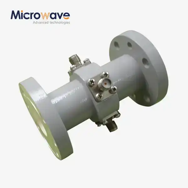
At their core, these precise instruments change the strength of signals by adding controlled resistive or absorptive elements to the electromagnetic field that moves through waveguide structures that are either rectangular or circular. Two main types of processes are used in design: resistance blade insertion and rotating polarization methods. The resistive vane method involves slowly entering a dielectric card covered with a material that loses electricity into the area with the strongest electric field. The deeper the insertion, the higher the attenuation. To regularly absorb energy, rotary vane designs use polarization rotation physics to turn a resistant element so that it is perpendicular to the direction of the signal's electric field. In high-frequency satellite uses, waveguide systems are different from their coaxial cousins because they keep the signal's frequency while lowering its volume.
Frequency Coverage and Performance Metrics
Satellite ground systems work with a wide range of frequency bands, from L-band data links (1–2 GHz) to Ka-band internet services (26.5–40 GHz) and even experimental Q-band frequencies (33–50 GHz). From making parts for these bands, we know that waveguide variable attenuators have very flat insertion loss across their working bandwidth—usually less than 0.5 dB at the zero attenuation setting—while keeping voltage standing wave ratios below 1.15:1. This low VSWR is very important for protecting Vector Network Analyzers while transmitters are being characterized or when making sure measurements are always the same in antenna pattern verification. In satellite modem tests, the attenuation accuracy standard, which is usually ±0.5 dB or tighter across the adjustment range, has a direct effect on how the link budget is calculated and how the bit error rate is predicted.

Critical Satellite Applications
These gadgets are chosen by procurement engineers for three mission-critical situations in satellite systems. Waveguide variable attenuators are used to test uplink power control. They mimic rain fade conditions, which is when signals weaken by 10 to 15 dB because of tropical storm cells. This lets system designers check adaptive coding and modulation levels without having to wait for bad weather. In high-power amplifier stability tests, they lower the TWTA output from kilowatts to milliwatts so that it can be used as input on a spectrum analyzer. This keeps the equipment from breaking and records data on harmonic distortion. The third important use is antenna feed network balance. This is where techs change the signal levels across multiple beam-forming elements to get even lighting and reduce sidelobe interference in multibeam satellite packages.
Comparing Waveguide Variable Attenuators with Other Types
Waveguide Versus Coaxial Architectures
When makers of satellite systems look at reduction methods, they have to choose between waveguide and cable solutions. Coaxial variable attenuators work best in small tabletop setups and lower frequency bands because they have threaded ports that allow for easy connection without tools and take up less space. However, waveguide versions are better in situations where a lot of power needs to be handled. They can often handle continuous wave power of more than 300 watts, while precision coaxial models can only handle up to 50 watts. The air-dielectric nature of waveguide transmission gets rid of the need for Teflon or polyethylene covering in cables. This lowers dielectric losses at millimeter-wave frequencies, where coaxial lines lose 3–5 dB/meter of signal strength. When it comes to serving W-band (75–110 GHz) study sites, procurement teams find that cable options are no longer useful, leaving waveguide as the only option.
Fixed Versus Variable Design Trade-Offs
Fixed waveguide attenuators are a good deal because they are steady, so they don't wear out as quickly, and their prices are sometimes 40% lower than changeable models. This cost-benefit goes away in testing settings that change the signal level often. To adapt to different test conditions, replacing a set 10 dB unit with a 20 dB unit takes time and causes mistakes in the connection every time the flanges are torqued. This process can be sped up by waveguide variable attenuators, which turn it into a simple gear change or motor-driven control signal. This cuts the time it takes to set up a measurement from minutes to seconds. The practical freedom is especially useful in satellite payload integration facilities, which have to test and confirm dozens of signal level combos every day across a wide range of temperatures and shaking levels.
Design Principles and Technical Specifications
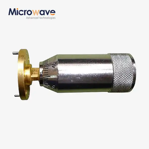
Mechanical Construction Elements
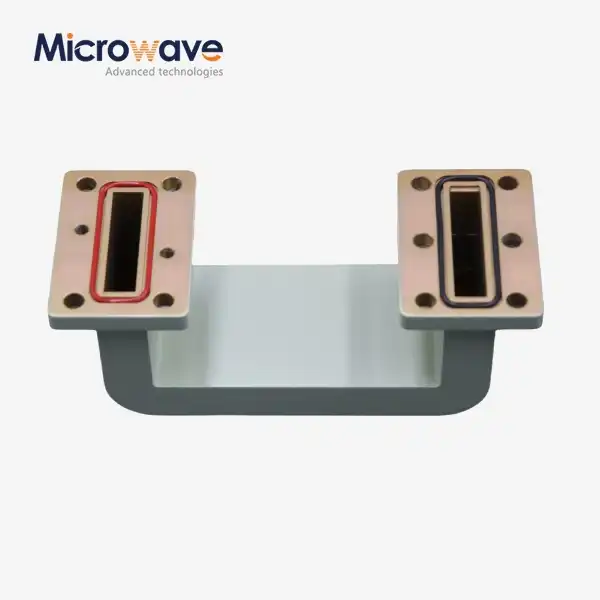
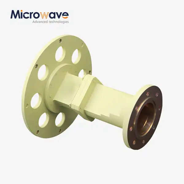
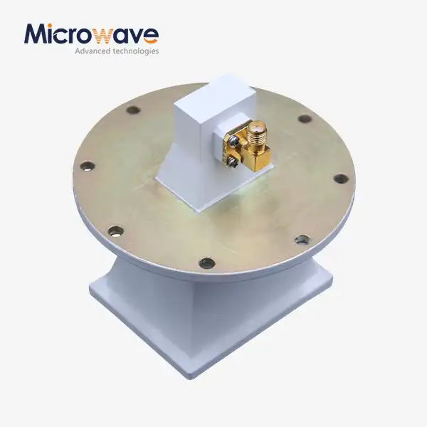
Micrometer-drive kits are connected to the resistance element through sealed rotary bearings or linear actuators. This is how these devices work with precision mechanics. To make sure the dial reading is within 0.1 dB of the real attenuation, premium implementations use ball-bearing guides and backlash-compensated gears. During production acceptance testing, we confirm this specification through swept-frequency network analysis. For X-band and lower frequencies, housings are usually made of an aluminum alloy. For Q-band and higher frequencies, where surface finish directly affects insertion loss, housings are made of gold-plated copper or electroformed nickel. Waveguide flange connections have standard sizes—UG-series specifications in North America and IEC specifications for purchases in Europe. Flatness limits are kept to 0.0005 inches to stop RF leaks and keep the stated VSWR performance across joining cycles.
Electrical Parameter Interdependencies
Understanding how important electrical standards relate to each other helps procurement experts read datasheets correctly. Your measurement system's noise floor penalty is set by insertion loss at zero. For every 0.3 dB of extra loss, receiver sensitivity drops by about 7% in digital communication lines. In vector measurement applications, phase stability across the attenuation range is very important. Designs with rotary vanes have almost no phase shift variation, while designs with resistive vane types may bring 30 to 60 degrees of phase change from 0 to 40 dB attenuation. Temperature coefficient standards, given in decibels per degree Celsius, show how attenuation changes from -20°C to +70°C, which is the temperature range that most uncontrolled ground station equipment rooms are in. To keep link budget gaps over yearly temperature changes, high-reliability satellite projects often need parts with temperature factors below ±0.01 dB/°C.
Power Handling Thermal Management
When high input power is used with waveguide variable attenuators set to the middle range of attenuation levels, the thermal design problem gets worse. Let's say 100 watts of power are sent into the device, which is set to a 20 dB reduction. Of that power, 99 watts must be lost as heat in the resistance element and waveguide case. Temperature-driven attenuation drift, shorter component life, or catastrophic failure through resistive film delamination can happen when thermal design isn't done right. Our engineering method uses finite element thermal modeling to figure out the right size of heat sinks and choose clay materials that can absorb heat and keep their loss tangent properties stable across a wide range of temperatures. Procurement specs need to include average and peak power rates, duty cycle limits, and mounting surface temperature needs for high-power satellite uplink test uses to avoid failures in the field.
Procurement Guide: Choosing and Buying Waveguide Variable Attenuators
Matching Specifications to Deployment Requirements
The buying process starts with making sure that the frequency band needs are clear and in line with the working frequencies of the satellite. For example, C-band Earth stations need WR-187 waveguide sizes, while Ka-band sites need WR-28 or WR-34 sections. The attenuation range needed depends on the test situation. For example, to measure receiver sensitivity, a 60-dB dynamic range is usually needed, while to check emitter uniformity, a 30-dB range is plenty. Environmental requirements separate commercial-grade parts that can work in climate-controlled labs from ruggedized versions that can be used outside in coastal or desert climates. If your ground station works above 3,000 meters, where air density is lower, ask providers about altitude derating factors. This is because lower air density makes convective cooling and voltage breakdown limits less reliable. Lead times can be very different. Items from the store ship within weeks, but custom waveguide band setups or specialized flange connections can take 8–12 weeks, which is important to know when planning a satellite launch campaign.
Evaluating Suppliers and Certification Requirements
Manufacturers you can trust have quality management systems that are in line with ISO 9001. They also give you mill test results that show readings of insertion loss, VSWR, and attenuation accuracy that can be tracked back to national measuring centers. In our temperature-controlled testing facilities, we use calibrated Vector Network Analyzers to check the performance of our waveguide components from DC to 110 GHz. This way, we can give buyers verified performance data instead of just nominal specs. European satellite operators will have to keep RoHS compliance paperwork, and U.S. defense companies will need it more and more to follow environmental rules. When you buy in bulk, you can save 15–25% on costs by joining orders for waveguide variable attenuators and related feed network parts or buying multiple waveguides of the same size. However, for normal stock items, the minimum order quantity is five units, and for special designs, it's three units.

Advantages of Using Waveguide Variable Attenuators in Satellite Systems
Superior Signal Integrity and Measurement Accuracy
The practical benefits are most clear in how accurate measurements are and how well the system is described. As engineers check the performance of a satellite transponder, they use waveguide variable attenuators to set the exact input power levels at the low-noise block downconverter. This lets them take accurate measures of gain compression and intermodulation distortion, which are used to figure out the payload capacity. The ability to make continuous adjustments gets rid of the discrete step limits of switched attenuator networks. This lets technicians find exact threshold points, like the input power level that sets off the automatic gain control, with resolution limited only by the drive mechanism and not by the attenuation values that are available. This fine-grained control means that link budget gaps are smaller and system acceptance decisions are made with more confidence when testing multimillion-dollar satellite ground infrastructure.
Enhanced System Adaptability and Lifecycle Economics
When compared to coaxial options, which can move due to connection wear and dielectric age, quality waveguides don't need to be calibrated as often because they are more stable at high temperatures. For satellite projects with 15-year working lives, parts that work well even after thousands of adjustments and changes in temperature are useful. Since there are no active semiconductor elements, there are no failure causes for PIN diode attenuators. Also, the design is completely dormant, so it is not affected by electromagnetic pulses, which is important for defense-related satellite communication facilities. Longer mean time between failures lowers maintenance costs. For expensive waveguide variable attenuators, this time is usually over 50,000 hours, compared to 20,000 hours for similar coaxial units. These benefits in dependability lead to lower total costs of ownership, which makes it worth paying more at first for satellite Earth station operators who put uptime first.
Investing in precision-engineered variable attenuators positions satellite system integrators to meet increasingly stringent performance requirements as bandwidth demands escalate and frequency allocations migrate upward into challenging millimeter-wave bands. When it comes to the competitive satellite service market, these parts become force multipliers because they give you trust in your measurements and operating freedom.
Conclusion
Variable attenuation technology in waveguide form factor is a stable but still-evolving skill that is needed for today's satellite communication systems. When you combine physics-based working principles with precise mechanical engineering and back them up with a lot of test data, you get the measurement accuracy and practical dependability that satellite ground systems buyers need. As the industry moves toward higher-frequency Ka-band and Q/V-band allocations to meet the growing demand for data flow, waveguide systems continue to have technical benefits over other architectures. Specification analysis, buyer approval, and lifetime cost models are used to make sure that procurement choices for ground stations are based on accurate information that lets them work as planned for many years to come.
FAQ
Q1: What distinguishes rotary vane from resistive vane variable attenuators?
The polarization rotation principles behind rotary vane designs make them very stable in terms of phase—usually less than 5 degrees across the whole range of attenuation—which makes them perfect for vector network analysis and measurements that depend on phase. Resistive vane types add absorbing material to the electric field of the waveguide. They are smaller and cheaper, but they introduce a phase shift that gets worse as the attenuation setting is changed.
Q2: How does frequency affect attenuation accuracy in satellite bands?
Because they are built on polarization, rotary vane attenuators can reduce signal levels almost regardless of frequency, and they can keep their accuracy within ±0.5 dB across the entire waveguide bandwidth. Resistive vane types are slightly sensitive to frequency and usually need adjustment factors of ±1 dB across octave bandwidths. This is explained on the calibration data sheets that come with each unit.
Q3: Can these components handle high-power satellite uplink testing?
Power handling depends on the design. Regular lab units can handle 10–50 watts of continuous wave, while high-power versions with better heat sinking and ceramic absorptive elements can handle 300+ watts. Always be clear about your peak and average power needs when you're buying something to make sure the thermal design is right and to avoid problems in the field during emitter evaluation efforts.
Partner with ADM for Premium Waveguide Variable Attenuator Solutions
Satellite ground system installers all over the world can benefit from Advanced Microwave Technologies Co., Ltd's more than 20 years of experience making specialized products. Our line of waveguide variable attenuators covers bands from L-band to W-band and has rotary vane and resistive vane designs that can be changed to fit your needs for power handling, accuracy, and weather factors. As a provider that is ISO 9001:2015 approved and can measure up to 110 GHz, we help buying teams by providing unique designs, fast development, and full test paperwork that speeds up the approval process. Talk to our engineering team at craig@admicrowave.com about the satellite communication parts you need and find out how working with a trusted waveguide variable attenuator maker can make your buying process easier while still meeting mission-critical performance standards.
References
1. Rizzi, P.A. (1988). Microwave Engineering: Passive Circuits. Prentice Hall International Editions.
2. Skolnik, M.I. (2008). Radar Handbook, Third Edition. McGraw-Hill Professional.
3. Maral, G. & Bousquet, M. (2002). Satellite Communications Systems: Systems, Techniques and Technology, Fourth Edition. John Wiley & Sons Ltd.
4. IEEE Standard 149-1979. IEEE Standard Test Procedures for Antennas. Institute of Electrical and Electronics Engineers.
5. Pozar, D.M. (2011). Microwave Engineering, Fourth Edition. John Wiley & Sons.
6. Ippolito, L.J. (2008). Satellite Communications Systems Engineering: Atmospheric Effects, Satellite Link Design and System Performance. John Wiley & Sons Ltd.