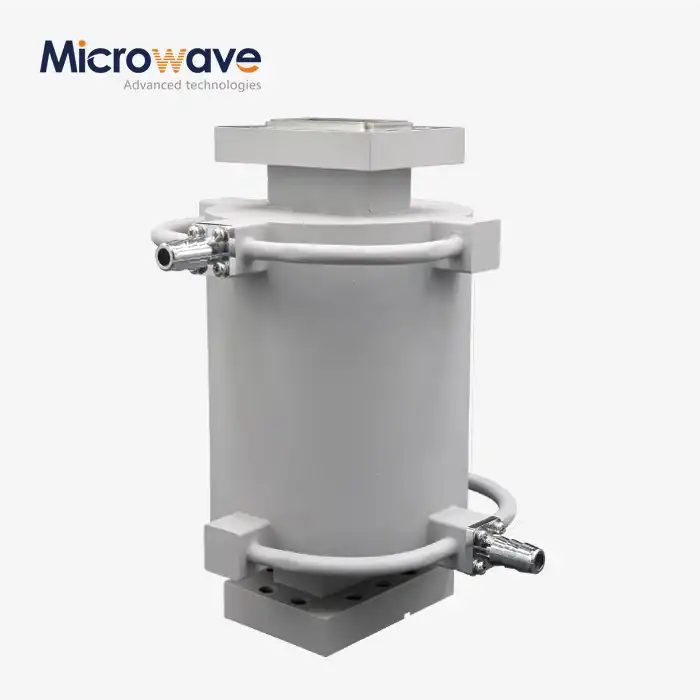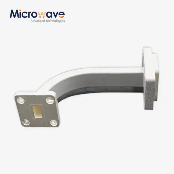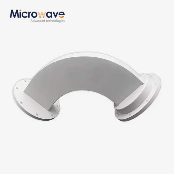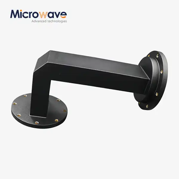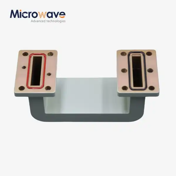
Double-bend Waveguide
Double-bend Waveguide for Microwave Systems — Precision Signal Routing in Constrained Spaces
When system layout demands RF routing across two non-coplanar axes, a double-bend waveguide provides a structurally rigid solution that a single-plane bend or flexible section cannot replicate. ADM manufactures these components across X-band, Ku-band, and Ka-band, achieving typical VSWR below 1.10:1. With in-house testing capability spanning 0.5 GHz to 110 GHz and over 20 years of microwave engineering practice, ADM supports both standard catalog configurations and fully custom bend geometries.
What Is a Double-bend Waveguide?
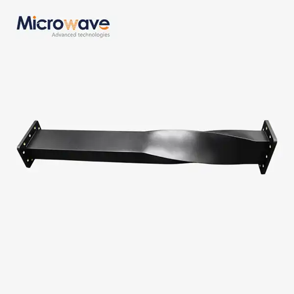
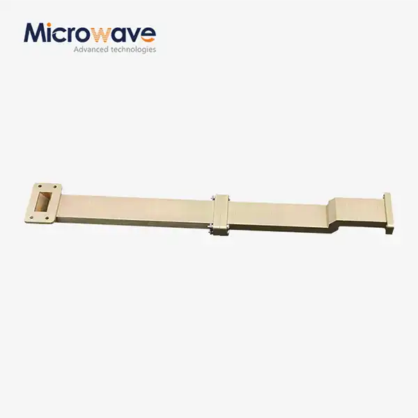
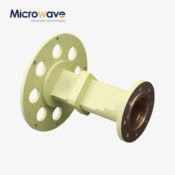
A product incorporates two curvatures — orthogonal, compound, or custom-angle — within a single rigid assembly. This configuration allows connection between waveguide ports that are offset along more than one axis, which is a common constraint in compact aerospace assemblies, dense rack-mounted telecom hardware, and satellite payload structures.
The rigid construction preserves phase stability across thermal cycles and eliminates the insertion loss penalty associated with flexible waveguide sections. Bending radii are calculated to exceed two wavelengths at the operating frequency, which suppresses mode conversion and signal reflection at each curve. TE/TM mode purity is maintained along the full signal path.
Integrating two bends into one machined assembly also removes the intermediate flange interfaces that would otherwise be required if two separate single-bend components were connected in series, reducing the number of potential reflection points in the signal chain.

Key Technical Specifications
Parameter | Specification |
Component Type | Passive waveguide transmission component |
Configuration | Two integrated bends (compound or orthogonal) |
Typical VSWR | < 1.10:1 across the operating bandwidth |
Supported Bands | X-band, Ku-band, Ka-band |
Materials | OFHC Copper, Aluminum 6061, Brass |
Surface Treatment | Silver or Gold plating + anti-corrosion passivation |
Flange Standards | CPR, UBR, PBR (EIA standard interfaces) |
Bending Radius | Typically > 2 wavelengths |
Dimensional Tolerance | Per MIL-DTL-85 standards |
Testing Frequency Range | 0.5 GHz – 110 GHz (ADM in-house capability) |
Materials and Construction
ADM manufactures double-bend waveguides from three primary materials, selected based on application requirements:
· OFHC Copper — Preferred where high thermal conductivity and low skin-effect loss are both required, particularly in high-power environments.
· Aluminum 6061 — The standard choice for weight-sensitive platforms such as airborne systems, offering a practical balance of mechanical strength and electrical conductivity.
· Brass — Suited to standard laboratory and ground-based communication applications.
To cut down on skin-effect losses, the insides are plated with silver or gold, and then they are passivated to stop corrosion. Split-block CNC machining lets you finetune the internal geometry, ridge alignment, and mating surfaces for the flanges, all of which have a direct effect on the VSWR at each contact.
Performance Characteristics
Through cycles of thermal expansion and contraction, phase stability is kept. This is important for satellite payloads and outdoor SATCOM gear that works in a wide range of temperatures and has receivers that are sensitive to phase shifts.
The dielectric properties of the air or pressurised gas inside the waveguide cavity, not the structure, determine how much power the part can handle. This means that it can meet the needs of high-power radar pulse transmission.
The single-assembly approach is better for keeping the signal integrity. The two bends are machined into one part, so there is no need for the intermediate flange pair that comes with a two-component system. This means that the signal path does not have any reflections from those flanges.
Application Scenarios
Aerospace and Defence — This part is used in airborne fire-control radars and missile seeker assemblies. It sends RF pulses from power amplifiers to gimbaled antenna arrays inside tight fuselage envelopes and meets structural requirements for environments with high G-load and vibration.
Satellite Communication (SATCOM) — Deployed in High Power Amplifier subsystems and feed networks to connect up-converters to antenna feed horns where port alignment is offset due to thermal management layout constraints.
Medical and Industrial Accelerators — Used in linear accelerators (LINACs) for cancer treatment and cargo scanning systems, they send RF power from klystrons to holes that speed things up. For these uses, you need materials that can work in vacuum and surface processes that don't let out gases.
Telecom Infrastructure — Allows for signal routing that makes the best use of space in crowded ground-based communication enclosures where standard straight sections can't fit the shape.
Customization Options
Custom configurations are available to match specific system integration requirements:
· Non-standard bend angles (including angles such as 35° or 72°) are achievable via CNC machining without requiring new casting molds, which reduces tooling cost and lead time for low-volume custom orders.
· Vacuum-compatible versions with outgassing-compliant materials, vented or hermetically sealed flange designs, and vacuum-rated gaskets.
· Custom flange interfaces following CPR, UBR, or PBR standards based on your existing system hardware.
· Material selection guidance based on weight budget, thermal environment, and conductivity requirements.
ADM's engineering team can review your port positions and enclosure constraints to recommend a bend geometry that meets both electromagnetic path-length and mode-integrity requirements.
Quality Assurance and Testing
Every double-bend waveguide is tested in ADM's in-house microwave testing facility, which includes a 24 m Microwave Darkroom and an Antenna Plane Near and Far Field Measuring Recombination Chamber. Insertion loss, VSWR, and signal behavior are measured across the full 0.5 GHz to 110 GHz range.
Dimensional inspection follows MIL-DTL-85 tolerances. Flange mating surfaces are precision-machined and verified to prevent the capacitive discontinuities that produce VSWR spikes at connector interfaces.
FAQ
Q: How well does the VSWR usually work?
A: The typical VSWR is less than 1.10:1 across the operating bandwidth. This is possible with bending radii greater than two wavelengths and internal geometry that is controlled by CNC.
Q: Are there models that work with vacuums?
A: Yes. Vacuum-compatible setups have materials that don't release volatile chemicals, no volatile coatings, and flange designs that are either hermetically sealed or vented and have vacuum-rated gaskets. Without these changes, standard catalogue versions can't be used in hoover environments.
Q: How do I tell you what the right bend angle is?
A: Tell ADM's engineers where your ports are located and what the limits of the enclosure are. CNC machining can make angles other than the usual ones, like 35° or 72°, without having to buy new tools, as long as the requirements for electromagnetic path-length and mode-integrity are met.
Q: Which flange standards can be used?
A: Interfaces for CPR, UBR, and PBR that meet EIA guidelines. You can get custom flange designs if you ask for them.
Q: How do I pick the right stuff?
A: Aerospace systems that need to be light can use aluminium 6061. OFHC Copper can be used for tasks that need a lot of power or a lot of thermal conductivity. Brass works with most ground-based systems. All three choices can have silver or gold plating on the inside.
Q: How long does it take to make a custom order?
A: The lead time depends on the complexity of the shape and the material chosen. Get a confirmed plan by contacting ADM with your needs.
Contact Us
Send your port layout, frequency band, and enclosure constraints for Double-bend Waveguide to craig@admicrowave.com for a technical review and delivery estimate.