





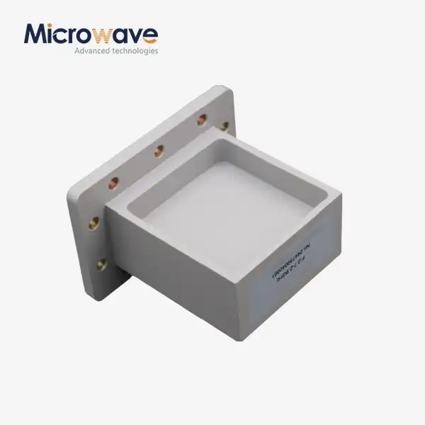
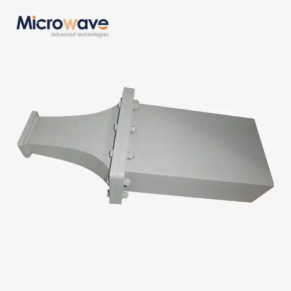
Custom WG to Coaxial Adapter
Tailored Design
Diverse Configurations
Wide Frequency Coverage
Low Insertion Loss
Custom WG to Coaxial Adapter — RF Signal Transition Solutions for Microwave Systems
Advanced Microwave Technologies Co., Ltd. (ADM) makes custom WG to Coaxial Adapter parts that move RF energy between waveguide and coaxial transmission lines with little signal loss. ADM has been working as a microwave engineer for more than 20 years and can handle frequencies from 1 GHz to 110 GHz, VSWR as low as 1.15:1, and insertion loss that is usually between 0.1 dB and 0.3 dB. Supports waveguide sizes that aren't standard, different coaxial connector interfaces, and tough environments like aerospace, satellite communication, and phased array radar.
What Is a WG to Custom WG to Coaxial Adapter and Why Does It Matter?
A waveguide-to-coaxial adapter is a passive RF part that changes the main electromagnetic mode inside a waveguide, which is usually TE10, into the coaxial line's TEM mode. There is either a probe-launch (E-field coupling) or a loop-launch (H-field coupling) mechanism inside the adapter body that changes the mode.
Most of the time, off-the-shelf adapters can't meet the exact needs of complex RF systems. An impedance mismatch makes signals bounce back, power flow slows down, and system performance goes down. A bad interface can make a system fail in high-density phased array radars or places that are completely shut off. These problems can be fixed with a custom adapter that is made to fit your exact frequency band, mechanical envelope, power level, and connector type.
Key Design Features
Customised Style
Each adapter is custom made to meet the needs of the customer, including non-standard frequency bands, unique mechanical dimensions, and unique flange configurations that can't be found in catalogue parts.
Different Configurations of Connectors
You can choose from SMA, N-Type, TNC, 2.92 mm (K), and 2.4 mm connector interfaces. Right-angle (broad wall probe) and end-launch inline designs are two types of launch orientations. Right-angle designs usually have a wider bandwidth and can handle more power, while end-launch designs work best for inline installations that don't have a lot of room.
Wide Frequency Coverage
The frequency range covers L-Band to W-Band, or 1 GHz to 110 GHz. This range supports both standard communication systems and millimeter-wave radar and satellite uses.
Low Loss of Insertion
Insertion loss is usually kept between 0.1 dB and 0.3 dB to protect the integrity of the signal over the whole working band.


Technical Specifications
Parameter | Specification |
Frequency Range | 1 GHz – 110 GHz (L-Band to W-Band) |
VSWR | <1.15:1 (narrowband) / <1.25:1 (broadband) |
Insertion Loss | 0.1 dB – 0.3 dB (typical) |
Waveguide Type | Rectangular, double-ridged, non-standard / half-height |
Coaxial Connector Types | SMA, N-Type, TNC, 2.92 mm (K), 2.4 mm |
Launch Mechanism | Probe-launch (E-field) / Loop-launch (H-field) |
Body Materials | OFHC Copper, Tellurium Copper, Aluminum 6061-T6 |
Surface Treatment | Silver or gold plating (MIL-DTL-45204 / ASTM B700) |
Power Handling | Up to kilowatt-level CW (air dielectric, large connector) |
Sealing Options | IP67 / IP68 (O-ring flange + hermetic connector) |
Thermal Shock Range | -55°C to +125°C |
Materials and Surface Treatments
The choice of body material has a direct effect on weight and electrical performance. Copper from OFHC has the best skin-depth losses and the best electrical transmission. Tellurium copper makes it easier to work with while still being a good conductor. Aluminium 6061-T6 is used when weight is important, like on platforms that are in the air.
Surface plating stops oxidation and lowers resistive losses. Gold plating is used for high-frequency precision uses or environments that are likely to rust. Silver plating is usually used across all microwave bands. All plating meets the requirements of MIL-DTL-45204 or ASTM B700.
Applications
ADM's custom WG to coaxial adapter products are used across a range of industries and system types:
· Satellite Communication — signal feed transitions in ground terminals and space-qualified assemblies
· Aerospace and Defense — phased array radar feed networks, electronic warfare subsystems, and hermetically sealed avionics
· Microwave Measurement — VNA port extensions and calibration reference paths from 0.5 GHz to 110 GHz
· 5G and Telecom Backhaul — outdoor mobile backhaul nodes requiring IP67/IP68-sealed interfaces
· Research and Test Labs — wideband test bench configurations requiring low-reflection transitions
Quality Control Process
Before being sent out, every adapter goes through a structured inspection process. A Vector Network Analyser (VNA) is used to check the electrical performance by comparing S11 (return loss) and S21 (insertion loss) to the original simulation data.
Coordinate Measuring Machine (CMM) tools are used in mechanical checking to check the flatness of the flange, the depth of the pins, and the concentricity of the connectors. Testing with salt spray according to ASTM B117 shows that plating is resistant to corrosion for use in marine and outdoor settings.
Thermal shock cycling from -55°C to +125°C and vibration testing make sure that the internal probe assembly stays stable in rough conditions for high-reliability applications. Each shipment comes with a Certificate of Conformance (CoC) that lists test results and material traceability.
ADM has a 24 m Microwave Darkroom and test facilities that work from 0.5 GHz to 110 GHz. These allow for full performance testing across the whole frequency range.
Customization and Lead Time
The engineering team at ADM works on both new designs and changes to custom WG to coaxial adapter configurations that are already in place. For new designs, the process usually takes 3–4 weeks for engineering modelling and then 4–6 weeks for precise machining and plating. Most of the time, small changes to specifications can be made faster.
It is possible to support non-standard and half-height waveguide designs by recalculating the cutoff frequency and improving the impedance matching circuit so that the transition to the coaxial port is smooth.
FAQ
Q: What determines how much power these adapters can handle?
A: The amount of power it can handle relies on the dielectric material used and the breakdown voltage of the coaxial connector. Long-wave (CW) power of up to kilowatts can be handled by air dielectric designs with big connectors like N-Type or 7/16 DIN.
Q: Can you make adapters for waveguide sizes that aren't standard?
A: Yes. ADM works with non-standard and half-height waveguides by changing the impedance matching circuit and figuring out the cutoff frequency again to make the connection to the coaxial interface smooth.
Q: What's the difference between an end-launch adapter and a right-angle adapter?
A: A right-angle adapter sends the probe through the waveguide's wide wall, which gives it a bigger bandwidth and better power handling. An end-launch adapter is inline and fits the needs of a small form factor, but its bandwidth is usually less.
Q: What kinds of versions do you have? Are they waterproof or hermetically sealed?
A: Yes. Using O-rings on the flange and hermetically sealed coaxial connections, adapters can be sealed to IP67 or IP68 standards. This means they can be used for naval platforms and outdoor backhaul nodes.
Q: What kind of test paperwork comes with each shipment?
A: Every item comes with a Certificate of Conformance (CoC) that has S-parameter VNA test results, records of how the materials were sourced, and dimensional check results.
Contact Us
Send your requirements for a custom WG to coaxial adapter to craig@admicrowave.com. ADM's engineering team will review your specifications and follow up with a technical proposal.
YOU MAY LIKE
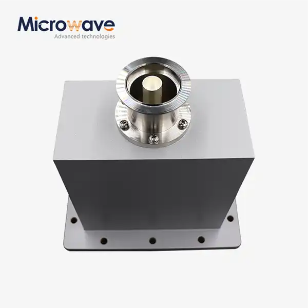 VIEW MOREEnd Launch Waveguide to Coaxial Adapter
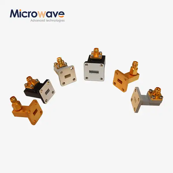 VIEW MORERight Angle Waveguide To Coaxial Adapter
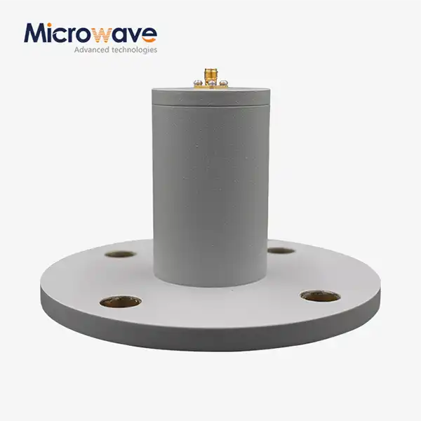 VIEW MORECircular Waveguide To Coaxial Adapter
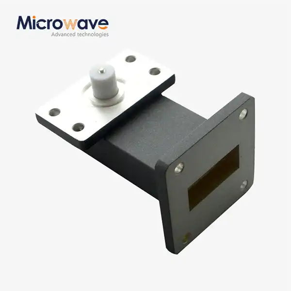 VIEW MORERight Angle Waveguide to Microstrip Adapter
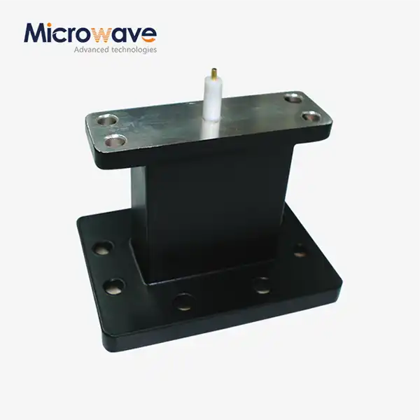 VIEW MOREEnd Launch Waveguide to Microstrip Adapter
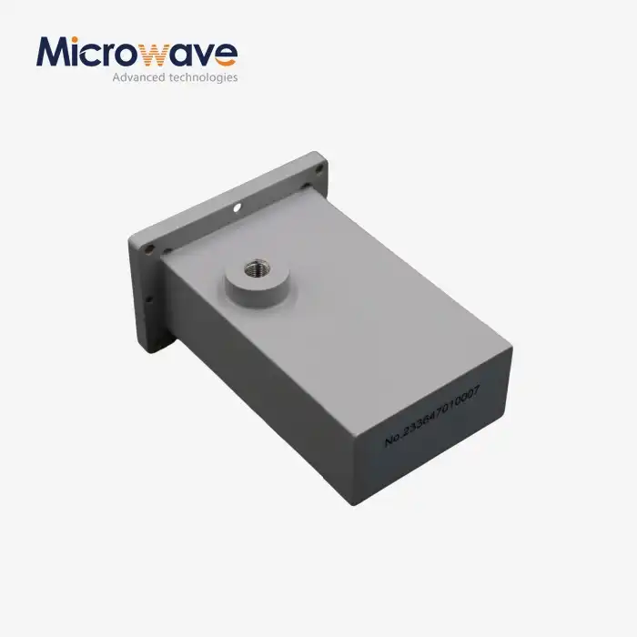 VIEW MOREWG Termination
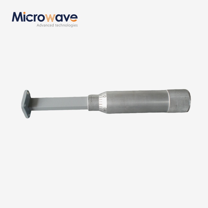 VIEW MOREWaveguide Sliding Termination
 VIEW MOREDouble Ridge Waveguide Termination
