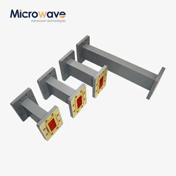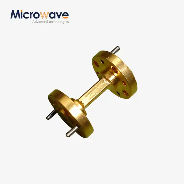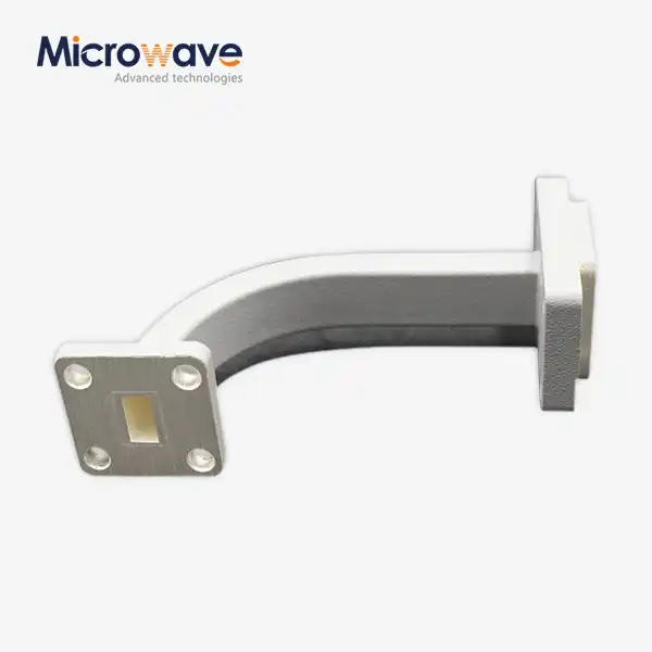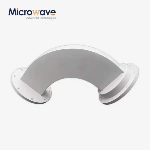
WG Twist
WG Twist Waveguide Components — Left & Right Hand, Custom Angles
The WG Twist from Advanced Microwave Technologies is a passive waveguide part that can turn the polarisation plane of a TE₁₀ mode signal by a set angle, usually 45° or 90°, without adding a lot of reflections or insertion loss. It comes in both left-hand and right-hand spinning, with custom twist angles and flange types, and waveguide sizes range from WR10 to WR430, including Double Rigid configurations. The VSWR is measured at − 1.10:1, and the insertion loss is less than 0.1 dB across all standard operating bands, from L-band to W-band.
What Is a WG Twist and How Does It Work?
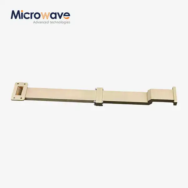
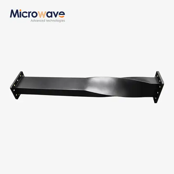
The polarisation plane of a propagating TE₁₀ mode is turned by a certain angle along a continuous taper profile by a product. The taper stops sudden changes in the component's internal shape. This keeps reflections low and lets it handle high peak power without the risk of arcing. The output flange comes out at the given rotation angle compared to the input, making a smooth transition between two waveguide sections that rotate at different angles.
The all-metal waveguide construction doesn't have a center conductor or a dielectric, which are both problems at higher frequencies when it comes to power handling. Coaxial adapters are used for similar routing tasks.
Frequency Coverage and Compatible Waveguide Sizes
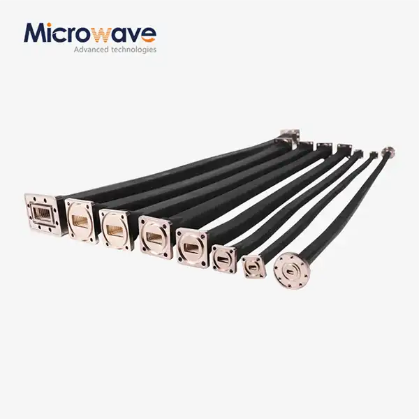
The range of products includes standard waveguide sizes from WR10 to WR430, which work with most common microwave system designs from L-band to W-band.
Waveguide Size | Frequency Band | Approximate Frequency Range |
WR430 | L-Band | 1.72 – 2.60 GHz |
WR284 | S-Band | 2.60 – 3.95 GHz |
WR187 | C-Band | 3.95 – 5.85 GHz |
WR137 | C/X-Band | 5.85 – 8.20 GHz |
WR90 | X-Band | 8.20 – 12.40 GHz |
WR62 | Ku-Band | 12.40 – 18.00 GHz |
WR42 | K-Band | 18.00 – 26.50 GHz |
WR28 | Ka-Band | 26.50 – 40.00 GHz |
WR15 | V-Band | 50.00 – 75.00 GHz |
WR10 | W-Band | 75.00 – 110.00 GHz |
Double Rigid configurations are also available for mechanically constrained installations.
Key Technical Specifications
Parameter | Specification |
Waveguide Size Range | WR10 – WR430, Double Rigid |
Twist Angle | Standard 45° / 90°; custom angles available |
Twist Direction | Left-Hand / Right-Hand |
VSWR | ≤ 1.10:1 over operating bandwidth |
Insertion Loss | < 0.1 dB |
Flange Type | Standard EIA; custom flanges available |
Material | OFHC Copper / Aluminum / Brass |
Surface Finish | Silver (Ag) or Gold (Au) plating |
Compliance | MIL-DTL-85; EIA standard flange interfaces |
Materials and Surface Treatment
The conductivity, weight, and mechanical durability of WG Twist are all affected by the base material choice. There are three choices, depending on the needs of the application.
OFHC Copper is the best for high-power or low-loss applications because it conducts electricity the best of the three. Aluminium (6061-T6) has a good strength-to-weight ratio, which makes it useful for projects that need to be light or in the air. Brass is chosen when certain mechanical qualities or resistance to corrosion are most important.
The inside is covered with a silver (Ag) or gold (Au) coating. The chemical passivation of plating keeps it from oxidising. Over time, surface oxidation raises resistor losses and intermodulation distortion at microwave frequencies.
Power Handling and Structural Integrity
The electromagnetic field is spread out gradually along the twist length by the continuous taper shape. This keeps the fields from concentrating in one place, which can lead to arcing at high peak power levels. This is a problem that needs to be avoided in radar emitters and high-power satellite uplink systems.
The rigid, all-metal design can handle vibration and changes in temperature in tough places like radar installations, satellite ground stations, and platforms in the air.
For systems with pressurised waveguides, the design allows for internal pressurisation with nitrogen or dry air to keep the system running without an arc at high power levels.
Customization Options
Most installation shapes can be accommodated by standard 45° and 90° twist angles. ADM can accept full custom specs if your system layout needs a different rotation.
The following custom values are available:
· Custom twist angle (other than standard 45° and 90°)
· Left-hand or right-hand rotation direction
· Non-standard flange types to match existing waveguide hardware
· Material selection based on weight, conductivity, or environmental requirements
Custom orders go through an engineering review to confirm dimensional compatibility and electrical performance before production begins.
Applications
WG Twist components are used where the physical orientation of a waveguide run must change while maintaining signal integrity across the transition.
Typical applications include:
· Satellite communication systems — feed network alignment and polarization management
· Radar and defense systems — antenna feed assembly routing
· Aerospace installations — space-constrained airborne waveguide runs
· Microwave test and measurement — bench and rack-mount configurations
· Point-to-point microwave links — outdoor radio system installations
Quality Assurance and Testing
ADM operates a 24-meter Microwave Darkroom with an Antenna Plane Near and Far Field Measuring Recombination Chamber, with testing frequency coverage from 0.5 GHz to 110 GHz.
Each unit is tested for VSWR and insertion loss using Vector Network Analyzer (VNA) S-parameter measurement. Return loss better than –20 dB is required across the operating passband before shipment.
Dimensional inspection covers flange flatness and aperture tolerances to confirm proper mating with EIA-standard interfaces and prevent assembly misalignment in the field.
FAQ
Q: What's the difference between right-hand and left-hand styles?
A: Left-hand and right-hand refer to the direction of polarization rotation when viewed from the input flange. Which one is right relies on which way the output flange needs to face in order to line up with parts further down the waveguide run.
Q: Can the twist angle be set to something other than 45° or 90°?
A: Yes, ADM does take orders for unique twist angles. You tell the engineering team what rotation angle and flange type you need, and they will make sure it is possible and within limits before production starts.
Q: What kind of VSWR performance is given?
A: Standard units are rated at VSWR ≤ 1.10:1 for both left-hand and right-hand configurations across the full operating bandwidth of the given waveguide size.
Q: How do I pick the right stuff?
A: OFHC Copper works well in high-power and low-loss situations. Aluminium 6061-T6 is good for systems that need to be light. Brass is used when certain mechanical or anti-corrosion qualities are needed. All three choices can have Ag or Au finishing on the inside.
Q: Can these parts be used with waveguide devices that are under pressure?
A: Yes. The design allows for internal pressurisation with nitrogen or dry air, which is useful for high-power systems that need to be outside or in the air and need to avoid arcing.
Q: What is the best way to find out what size waveguide I need for my frequency range?
A: Use the table above to match the WR designation to your operating frequency. For technical advice, send your information to craig@admicrowave.com if your frequency is not in a standard range or if you are working with a unique type of flange.
Contact Us
For custom specifications or technical questions about WG Twist components, contact the ADM engineering team directly at craig@admicrowave.com.