





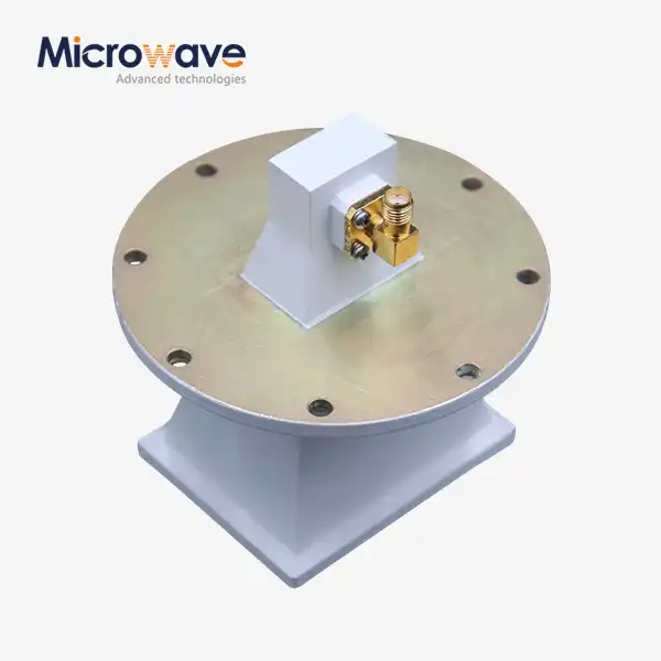
Pyramidal Linear Polarization Horn Antenna
Pyramidal Linear Polarization Horn Antenna — For Microwave & Millimeter-Wave Measurement, EMC, and Radar Applications
The Pyramidal Linear Polarization Horn Antenna from Advanced Microwave Technologies (ADM) operates across microwave and millimeter-wave frequencies, typically 0.3 GHz to 100 GHz. It flares outward in both the E-plane and the H-plane, gradually matching the resistance of the waveguide to that of free space. It is fed by a TE10 mode waveguide. The gain can be anywhere from 10 dBi to 25 dBi, and the cross-polarization isolation is more than 25 dB. The VSWR is usually less than 1.5:1. A standard waveguide port or a coaxial link can be used as an input.
What Is a Pyramidal Linear Polarization Horn Antenna?
A pyramidal horn antenna is made up of a waveguide that is rectangular and flares out in both the E-plane (direction of the electric field) and the H-plane (direction of the magnetic field). By slowly switching from waveguide impedance to free-space impedance (377 Ohms), this flare lowers signal reflection and boosts the efficiency of radiation.
Two things about its structure make it useful for measuring RF. First, the flared shape gets rid of the sudden change in impedance that happens in open-ended waveguides. This lowers the return loss across the operating band. Second, aperture size and flare angle can be used to figure out gain in theory. This is why this type of antenna is often used as a gain reference in calibration procedures.
The actual aperture stays pretty small when the gain is below about 22 dBi. The flare sizes of the E-plane and H-plane patterns control them separately. This lets engineers predict the beam characteristics without having to set up complicated feed networks.
Key Technical Specifications
Parameter | Specification |
Frequency Range | 0.3 GHz – 100 GHz (typical) |
Gain Range | 10 dBi – 25 dBi |
VSWR | < 1.5:1 (standard bandwidth class) |
Cross-Polarization Isolation | > 25 dB |
Polarization | Linear (vertical or horizontal) |
Input Type | Waveguide port or coaxial input |
Material | Precision-machined aluminum or copper alloy |
Surface Treatment | Chemical passivation (Alodine) or silver/gold plating |
Aperture Dimensional Tolerance | ±0.05 mm |
Power Handling | CW and peak pulse power (limited by waveguide breakdown voltage) |
Feed Mode | TE10 waveguide |
Materials & Construction
ADM's Pyramidal Linear Polarization Horn Antenna horn antennas are machined from aluminum or copper alloys. The size of the aperture is kept within 0.05 mm of the target, and the internal flare surface finish is closely monitored. A rough surface increases insertion loss, especially at millimeter-wave frequencies where the skin depth is low.
Some models are protected against oxidation and skin-effect losses by chemical passivation (Alodine) or precious metal plating (silver or gold). This is done in test settings where long-term dimensional stability is important.
These choices about how to build an antenna make it so that its gain and pattern performance stay the same across its entire operating band without needing to be adjusted mechanically on a regular basis.
Application Scenarios
Testing for EMC/EMI Compliance
Pyramidal horn antennas are a common way to test for both radiated emissions and radiated immunity in anechoic chambers that follow the ANSI and CISPR frameworks. Because of their focused beam and manageable size, they can be used to create a controlled field in susceptibility tests, such as in ISO 11451-compliant automotive test setups.
Setting the Gain and Range of the Antenna
This type of antenna is used as a standard in the Gain Transfer Method, which compares the power received from an unknown antenna to the known gain of the horn. This is possible because gain can be estimated from the antenna's size. Reference-grade units need to be calibrated at different times depending on how the lab manages quality and how the units are used.
Uses for Radar and Reflector Feeds
The pyramidal aperture gives off a fairly even amount of light when used as a feed element for parabolic reflectors in radar systems or point-to-point microwave lines. Matching the horn's beamwidth to the reflector's f/D ratio is important for controlling spillover and side-lobe levels. The antenna can also work as a transmitting or receiving unit that works on its own, or it can be used as a part of an array.
Quality Control Process
ADM applies a structured inspection workflow to each unit before shipment.
Dimensional Inspection: Aperture dimensions and flare angles are verified against ±0.05 mm tolerances. Internal surfaces are checked for pitting or oxidation that could degrade performance at high frequencies.
VSWR and Return Loss Sweep: Each unit undergoes a full-band VNA sweep. The standard pass criterion is VSWR below 1.5:1 or 2.0:1 depending on the bandwidth class, corresponding to less than 10% reflected power.
Gain Calibration: Standard gain variants receive individual calibration using the 3-antenna method. QC reports document Gain Factor (dB) and Antenna Factor (dB/m) at standard frequency steps.
Pattern and Cross-Polarization Verification: Far-field pattern tests confirm main lobe centering and symmetry. Cross-Polarization Discrimination (XPD) is measured to verify the antenna does not respond to orthogonal polarizations — a relevant parameter in dual-polarized system isolation.
Testing Facility — 24 m Microwave Darkroom
ADM operates a 24-meter Pyramidal Linear Polarization Horn Antenna Microwave Darkroom equipped with an Antenna Plane Near and Far Field Measuring Recombination Chamber, supporting flexible switching between near-field and far-field measurement modes.
Testing coverage spans 0.5 GHz to 110 GHz, covering both conventional microwave bands and millimeter-wave frequencies. Radiation characteristics, far-field gain, and pattern behavior are evaluated in this controlled environment before delivery.
Customization and Input Options
ADM offers flexible configurations to match system requirements. Input options include:
· Standard waveguide port (TE10 mode)
· Coaxial input (direct coaxial design)
· Waveguide with waveguide-to-coaxial transition (combined input)
Custom frequency ranges, gain levels, and connector types are available. Contact ADM's engineering team to discuss your specific application requirements.
FAQ
Q: What limits the lowest frequency that this antenna can handle?
A: As for A, the low-frequency cutoff is determined by the size of the waveguide feed section. Below the cutoff frequency of the waveguide, the signal weakens quickly and doesn't move through the construction well.
Q: Can circular polarisation work with this antenna?
A: Not in the way it usually looks. Only linear polarisation can work with a pyramidal horn. To get circular polarisation, you need to either add an outside polariser, like a septum or dielectric vane, to the waveguide feed or change the shape of the antenna to something else, like a conical horn.
Q: How often should you clean up your standard gain horns?
A: The amount of time between calibrations depends on how often the unit is used, the lab's internal procedures, and whether the unit has been physically handled in a way that could change the aperture geometry. Any shape change to the aperture has a direct effect on the gain properties.
Q: Why is the phase center important for my use?
A: The phase center is where the energy seems to come from. Its position in relation to the aperture changes how the path length is calculated in radar or compact range setups. When using pyramidal horns for precise measurements, it's important to keep in mind that the phase center point changes slightly with frequency.
Q: What's the difference between a corrugated horn and a pyramidal horn?
A: The inside walls of a pyramidal horn are smooth, and it can handle linear polarisation. The E-plane and H-plane beamwidths are slightly different. A corrugated horn has grooved walls on the inside to get less cross-polarization and more rotationally symmetric patterns, but it is much more difficult to make and costs a lot more.
Q: What kinds of input connectors are there?
A: You can use a standard waveguide port (TE10 mode), a direct coaxial input, or a combined waveguide with an integrated waveguide-to-coaxial transition as an input type. You can talk to ADM's tech team about the different connector formats that are available based on the frequency range.
Contact Us
Reach our engineering team at craig@admicrowave.com to discuss your Pyramidal Linear Polarization Horn Antenna requirements.
YOU MAY LIKE
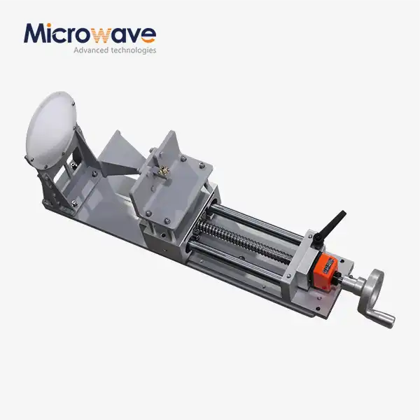 VIEW MOREFeed Fired Lens Antenna
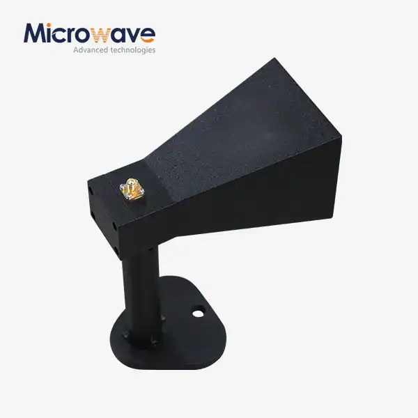 VIEW MOREMini Wideband Double-ridged Horn Antenna
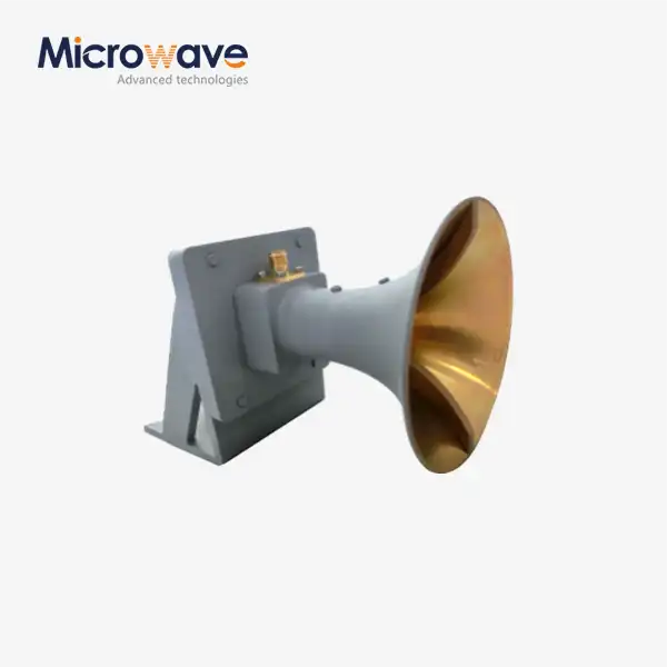 VIEW MOREUltra Double-ridged Horn Antenna
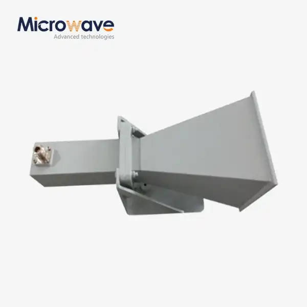 VIEW MORELadder Membrane Square Dual Circular Polarization Horn Antenna
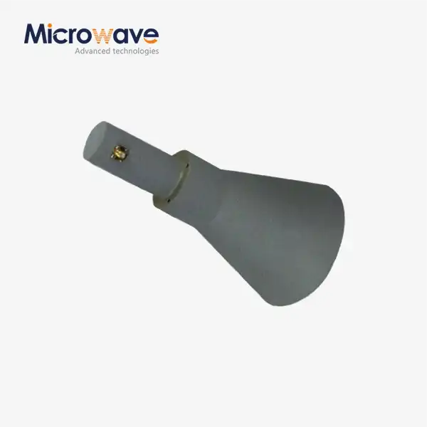 VIEW MORELadder Membrane Conical Dual circular Polarization Horn Antenna
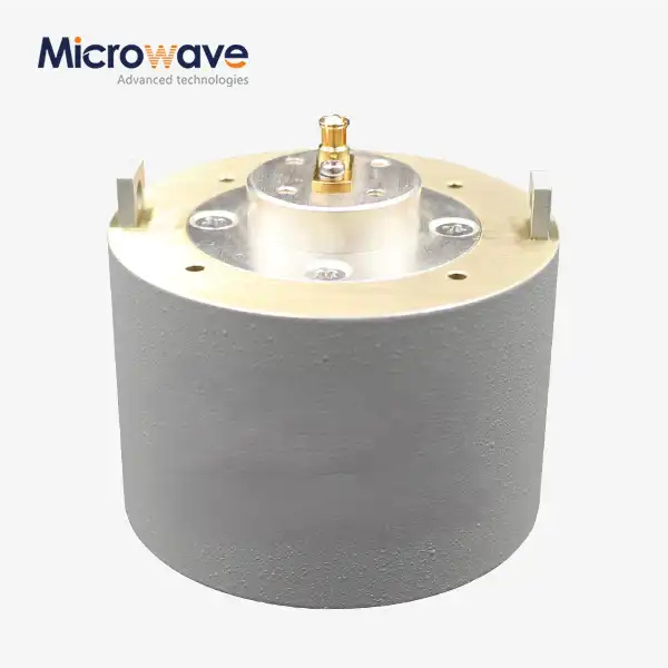 VIEW MOREPlanar Spiral Antenna
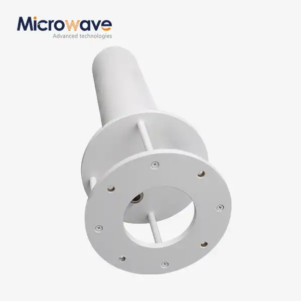 VIEW MOREQuadrifilar Helix Antenna
 VIEW MORECassegrain Antenna
