





Waveguide Transition Frequency Range Explained for Workshop
A waveguide transition is a passive microwave component that transfers RF energy between two different transmission media or waveguide sizes with minimal signal reflection. In workshop environments, understanding its frequency range is not optional — it directly determines insertion loss, return loss, and overall signal integrity. Whether you are working with X-band radar assemblies or Ku-band satellite ground stations, selecting a transition matched to your operating frequency band prevents impedance mismatch, suppresses parasitic modes, and protects sensitive amplifier hardware from reflected power.
Understanding Waveguide Transitions and Frequency Range
What Is a Waveguide Transition?
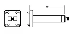
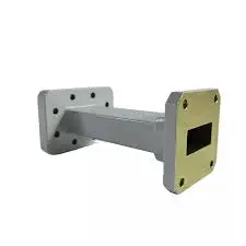
It's possible for a waveguide transition to connect two different types of transmission systems, like a rectangular waveguide to a coaxial connection or a WR-112 flange to a WR-90 flange. It changes the impedance of two ports by using a curved or stepped internal shape to make the characteristic impedances of both ports match up. Even a small change in size at microwave frequencies can cause reflections that hurt system performance if the transition isn't properly designed.
How Frequency Range Governs Performance
There is a set frequency below which the dominant TE₁₀ mode can't travel through a rectangular waveguide. Most of the time, the available bandwidth is between 125% and 190% of that level. For example, WR-90 covers the X-band from 8.2 to 12.4 GHz, while WR-75 covers the X-band from 10.0 to 15.0 GHz. When you use a transition outside of its rated band, it causes higher-order mode excitation and a fast rise in insertion loss, which are two problems that are hard to find in the field.
Design Principles: Dimensions and Materials
Where a transition works well is based on its internal shape. Tapered shapes have a bigger bandwidth, but they need to be longer. Stepped designs, also called Chebyshev-matched designs, cover a smaller band but fit tighter arrangements. Both types of material are important. Oxygen-free hard copper (OFHC) is the best conductor, while 6061-T6 aluminum is best for flying platforms that need to be light. To keep skin-effect losses in check, the internal surface roughness must stay below 63 micro-inches.
Key Frequency Ranges of Common Waveguide Transitions and Their Applications
Standard Waveguide Bands and Corresponding Types
The EIA standard gets waveguide names straight from the broad-wall measure. This is how common types relate to frequency:
- WR-137 (5.85–8.20 GHz, C-band): This type of antenna is commonly used in weather radar and maritime surveillance where it needs to be able to handle up to kilowatts of power.
- WR-90 (8.20–12.40 GHz, X-band): Fire-control radars in the air and tracking systems on the ground use it a lot. In good parts, the TE₁₀ dominant mode travels smoothly across the whole band with VSWR below 1.25:1.
- WR-75 (10.0–15.0 GHz, X/Ku overlap): In SATCOM earth stations, where low insertion loss (usually less than 0.15 dB) is a must, the WR-75 connects X-band emitters and Ku-band feed units.
The first thing a procurement engineer should do is make sure that the transition type matches the working band.
Real-World Application Connections
High-power amplifiers (HPAs) in satellite communications use WR-137 flanges, but the antenna feed may need a WR-90 or WR-75 input. This gap is filled by a tapered waveguide transition that doesn't add reflection spikes to the uplink band. 'Twist' and 'taper' transitions let aircraft radar signals go through a restricted airframe shape while still being able to handle MIL-STD-810 vibration and temperature changes. In both situations, the parts need to be frequency-matched. A difference of just 500 MHz outside the recommended band can make the VSWR higher than 1.50:1, which makes the emitter less efficient.
Procurement Value of Frequency-Matched Transitions
It's not just a matter of taste; buying a transition that is rated just right for your band also cuts down on system downtime. Power that is reflected by a high VSWR can damage solid-state power amplifiers (SSPAs) or klystron sources in a way that can't be fixed. Return loss is kept below -20 dB across the operating band by frequency-matched transitions from approved sources. This directly leads to more system uptime and lower repair costs.
Comparing Waveguide Transitions: Frequency Range vs Other Key Parameters
Waveguide vs Coaxial Adapters
Coaxial adapters are small and work well below 18 GHz for low-power tasks, but because they are dielectric-filled, they can only handle tens of watts of peak power. A square waveguide transition with an air insulator can handle peak power of kilowatts to megawatts. At Ka-band (26.5–40 GHz) and above, coaxial adapters also have more dielectric loss, which is why waveguide transitions are best for situations that need both high power and low loss.
Waveguide vs Microstrip Transitions
In active array feeds and combined antenna modules, microstrip-to-waveguide changes happen a lot. They have a lot of bandwidth, but they have a higher insertion loss (usually between 0.3 and 0.8 dB), and they can't handle changes in substrate temperature well. In tough environments and situations where loss is limited, like defense radar, a precision-made waveguide transition works better than a microstrip option in terms of both power and temperature.
Key Comparison Parameters
For your reference, the table below shows the main trade-offs between the different types of transition for engineering and procurement:
- Frequency range: Waveguide transitions follow EIA standard bands. At higher frequencies, coaxial connections are more flexible but not as good.
- Insertion loss: Waveguide-to-waveguide transitions usually have insertion loss of less than 0.1 to 0.3 dB, while microstrip transitions have insertion loss of 0.3 to 0.8 dB.
- Power handling: Air-dielectric waveguide designs can handle kilowatts of power, but the power level of a coaxial connection limits how much power it can handle.
- VSWR: Waveguide transitions made for precision applications get less than 1.10:1, while standard industrial grades stay below 1.25:1.
During the review of the bill of materials, these differences help buying teams avoid making expensive changes.
How to Measure and Optimize Waveguide Transition Frequency Performance in Your Workshop
Vector Network Analyzer (VNA) Testing
Before going into production, every waveguide transition should have its S-parameters swept across the full rated band to measure S11 (return loss) and S21 (insertion loss). If the S21 trace is smooth and doesn't have any resonance spikes, it means that there are no grinding flaws inside the hollow. By calibrating the VNA with a full two-port SOLT or TRL procedure at waveguide reference planes, systematic measurement error is eliminated, and the results stay within the limits set by ISO 17025.
Common Troubleshooting Scenarios
A rapid rise in insertion loss at a certain frequency is generally caused by one of three things: an error in the flatness of the flange that lets RF leak through, an internal burr that sets off a parasitic mode, or a connector pin that isn't lined up right in a coax-to-waveguide adapter. The first problem can be fixed by using a Coordinate Measuring Machine (CMM) to check that the lip is flat within ±0.02 mm. The second can be fixed by looking at it under a microscope and sweeping it again after it has been cleaned. The third problem is fixed by checking the torque on the hardware that mounts the connection.
Best Practices for Sustained Performance
Please follow these rules in your workshop:
- To keep measurement accuracy, calibrate your VNA before each test using standards that can be traced back to NIST or an equivalent national laboratory.
- Control ambient temperature while testing. Aluminum transitions get bigger at a rate of about 23 ppm/°C. In narrow-band assemblies, a 20°C change can move a resonance by several MHz.
- Check the thickness of the plating by XRF measurement before accepting the order for good. Copper oxide is lossy at microwave frequencies and grows over time in humid places. Silver plating at 50–100 micro-inches per MIL-G-45204 stops it from forming.
Consistently following these steps will increase the service life of your parts and protect your measurement data during customer audits.
Procurement Insights: Choosing and Buying Waveguide Transitions by Frequency Range
Supplier Selection Criteria
When a business-to-business buyer is looking for waveguide transitions for production projects, the following factors are the most important:
- Frequency range adherence: Make sure the supplier gives you VNA test data for each unit or batch, not just a list of specs from a catalog.
- Customization capability: Programs that need twist angles, flange pairings that aren't standard, or band coverage that goes beyond the EIA standard need a manufacturer with in-house machining and RF design support.
- Lead time and MOQ: Short lead times and low minimum order quantities lower program risk during the prototype phase. When making a lot of OEM parts, regular delivery times are more important than just the unit price.
- Post-sales support: Being able to get help from engineers with integration questions lowers the cost of having to redo work during system-level testing.
Pasternack, HUBER+SUHNER, Maury Microwave, and Rosenberger are all well-known brands in this field, and each has recorded frequency performance data for standard bands.
Documentation and Quality Requirements
For each serial number, defense and aerospace procurement teams need material certifications, plating records, and VNA sweep data that can be tracked. This level of traceability is a standard service that ISO 9001:2015-certified suppliers offer. Environmental test records — salt spray per ASTM B117, thermal cycling from −55°C to +85°C — are mandatory for maritime and airborne applications. It is common for serious suppliers to ask for these documents before placing an order. This is how you can tell the difference between serious suppliers and commodity brokers.
Conclusion
The waveguide transition frequency range is the most important factor that affects how it is designed, how well it works, and how much it costs. From selecting the correct EIA waveguide size to verifying VNA sweep data and environmental qualification records, each step depends on getting the frequency match right. For defense radar, SATCOM uplinks, or laboratory measurement systems, a properly rated transition keeps VSWR low, insertion loss controlled, and system uptime high. Taking time to understand these parameters before procurement prevents expensive late-stage redesigns.
FAQ
What determines the frequency range of a waveguide transition?
The broad-wall dimension of the rectangular waveguide sets the cutoff frequency for the dominant TE₁₀ mode. The usable frequency range typically spans 125%–190% of that cutoff. The waveguide transition geometry — tapered or stepped — and internal surface finish then determine how well the component performs across that range.
What VSWR should I expect from a quality waveguide transition?
Metrology-grade transitions achieve VSWR below 1.10:1. Standard industrial-grade units stay under 1.25:1. Values above 1.30:1 indicate a meaningful reflection that can damage high-power amplifiers over time.
Can I use a waveguide transition outside its rated frequency band?
Operating outside the rated band risks sparking higher-order modes and greatly increases insertion loss. For even moderate excursions — 500 MHz beyond the upper band edge at X-band — performance degradation is measurable and potentially damaging to the transmitter.
How do I verify plating quality before acceptance?
X-Ray Fluorescence (XRF) measurement confirms silver or gold plating thickness against the specification (typically 50–100 micro-inches). This is a non-destructive test that providers should perform and record as part of their quality control process.
What materials are appropriate for airborne applications?
6061-T6 aluminum finished with Alodine (chromate conversion coating) or silver plating is standard for airborne systems where weight reduction is the main limit. Oxygen-free hard copper (OFHC) is preferred for stationary ground systems where conductivity and solderability take priority.
Partner With ADM for Precision Waveguide Transition Solutions
ADM has provided accurate RF and microwave components to defense, satellite, and industry users for over 20 years. As a trusted waveguide transition maker, we offer ISO 9001:2015-certified components from C-band through W-band, full VNA sweep data with every order, and OEM customization with fast sample turnaround. Reach out to our engineering team at craig@admicrowave.com to talk your frequency range needs and receive a quote.
References
1. Pozar, D. M. Microwave Engineering, 4th ed. Wiley, 2011.
2. Montgomery, C. G., Dicke, R. H., & Purcell, E. M. Principles of Microwave Circuits. MIT Radiation Lab Series, Vol. 8. McGraw-Hill, 1948. Reprinted by IET, 1987.
3. IEEE Standard 521-2019. IEEE Standard Letter Designations for Radar-Frequency Bands. IEEE, 2019.
4. Electronic Industries Alliance (EIA). EIA Standard RS-359: Rectangular Waveguide. EIA, 1997.
5. Collin, R. E. Foundations for Microwave Engineering, 2nd ed. Wiley-IEEE Press, 2001.
6. Rizzi, P. A. Microwave Engineering: Passive Circuits. Prentice Hall, 1988.
YOU MAY LIKE
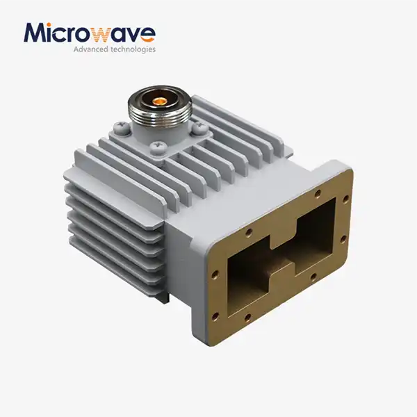 VIEW MOREHigh Power Waveguide to Coaxial Adapter
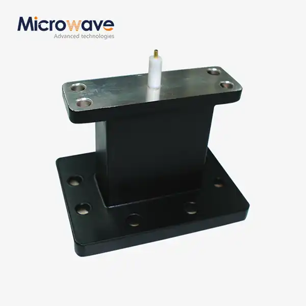 VIEW MOREEnd Launch Waveguide to Microstrip Adapter
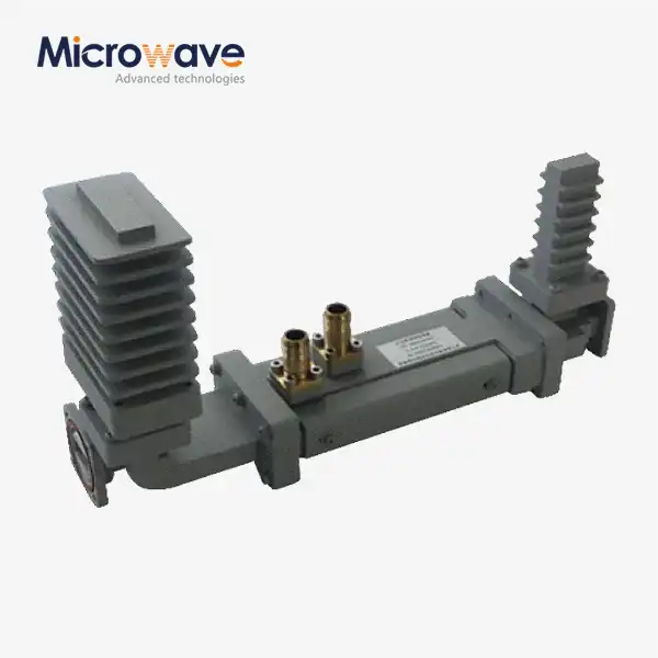 VIEW MOREHigh Power Waveguide Differential Phase Shift Isolator
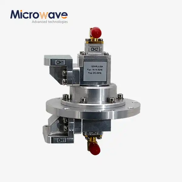 VIEW MOREWG Dual-Channel Rotary Joint
_1733738410152.webp) VIEW MORECoaxial Power Divider
VIEW MORECoaxial Power Divider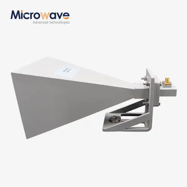 VIEW MOREStandard Horn Antenna
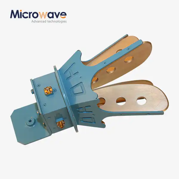 VIEW MOREOpen Boundary Dual Linear Polarization Four Ridged Horn Antenna
 VIEW MORELadder Membrane Conical Dual circular Polarization Horn Antenna
