Single or Dual? Matching a Coaxial Directional Coupler to Your Test Setup
Choosing between a single and dual coaxial directional coupler is one of those decisions that can quietly define the accuracy of your entire test setup. A coaxial directional coupler is a passive RF device that samples a fraction of electromagnetic power traveling in one direction along a transmission line, while maintaining high isolation from signals moving the other way. Whether you're monitoring forward power, measuring return loss, or building a reflectometer, picking the wrong configuration costs you time, money, and measurement confidence.
Understanding Coaxial Directional Couplers: Fundamentals and Applications
To properly compare configurations, it is helpful to know what these parts do inside a transmission line.
How Directionality Works
One way a directional coupler works is by connecting a small part of the main signal to a secondary port electromagnetically. The direction of the coupling lets it tell the difference between waves that are moving forward and waves that are being reflected. Not only is this a useful feature, but it's also the whole point. This distance is important for engineers at radar sites and satellite ground stations to be able to find impedance mismatches in real time without getting in the way of the main signal line.
Core Design Parameters That Matter
There are four things that determine how well an RF coupler works in the real world:
- Coupling Factor (6 dB to 40 dB): Controls how much signal is diverted to the coupled port. Tighter coupling means more sampled power but also slightly higher insertion loss on the main line.
- Directivity (>20 dB, ideally >30 dB): The single most important indicator of how well the device separates forward and reflected signals. Poor directivity leads to measurement errors that can be difficult to trace.
- Insertion Loss (<0.5 dB typical): The amount of signal lost on the main transmission path, excluding the intentional coupling loss.
- VSWR (<1.25:1 typical): Reflects how well the coupler matches the system impedance, usually 50 ohms.
These factors don't work alone; they work together. It is important to know the trade-offs when buying a coupler because ones that are built for wide bandwidth often have slightly worse directivity at the band ends.
Common Applications Across Industries
RF directed couplers are used for many different things. When 5G spread antenna systems are used, they check the live forward power and report antenna problems when they see high reflected power numbers. In aerospace radar, they feed into automatic level control loops that keep the output of the amplifier stable even when the temperature changes. They make up the measurement bridge in VNA-based test benches that splits signals that come in and signals that bounce back for accurate S-parameter extraction.
Single vs. Dual Coaxial Directional Couplers: Comparison and Decision Criteria
There is a clear structural difference between these two types, but the functional effects are more complex than most buyers first think.
What Makes a Single Coupler "Single"
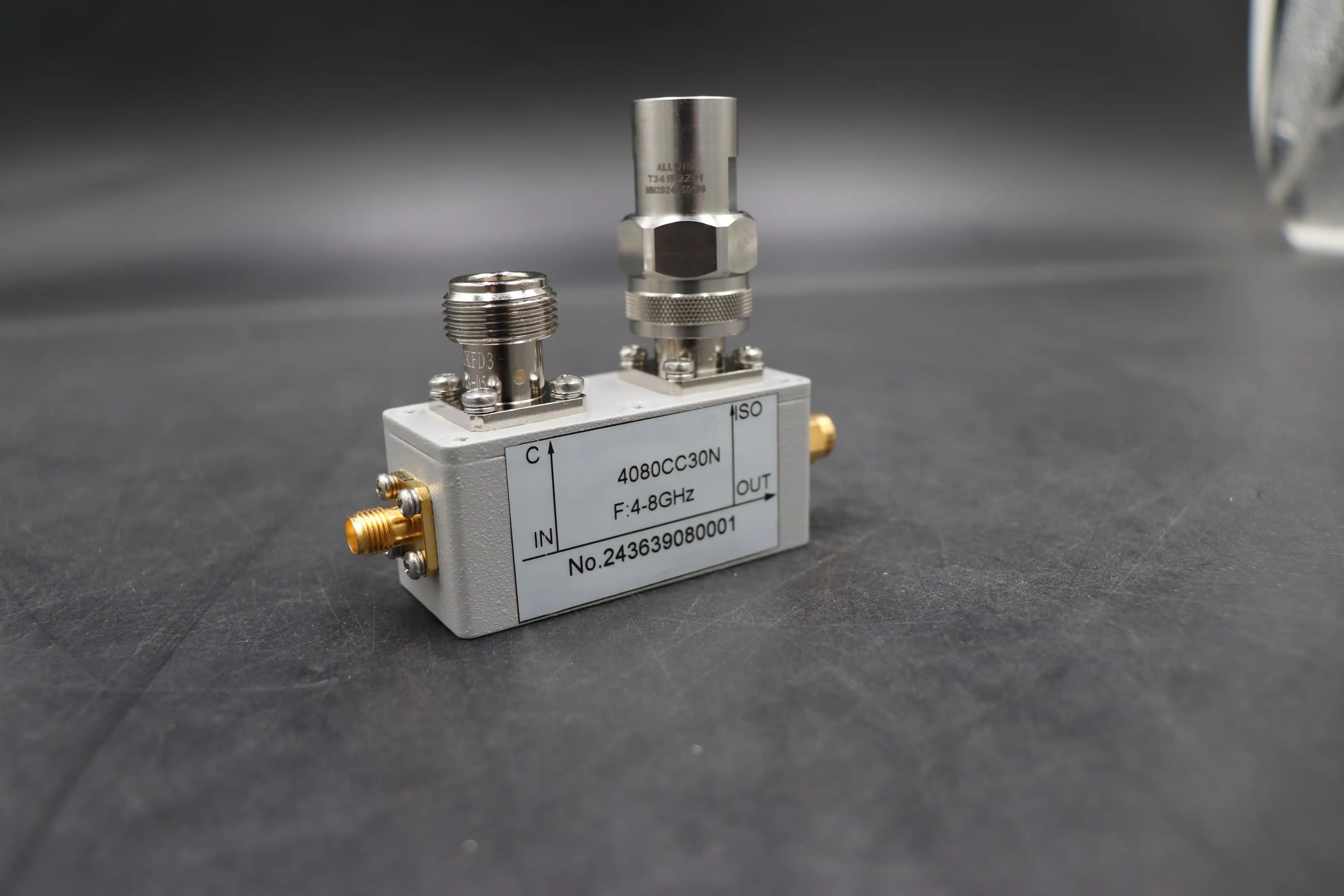
There is only one coupled port on a coaxial directional coupler , and it only captures one of the waves—either the forward or the reflected wave. It's the best choice when you only need to keep an eye on one direction. One unit can accurately measure output power, work as a power-leveling loop in an amplifier chain, and sample signals in only one direction. A simpler structure usually means less money and a smaller footprint, which is important in assemblies with limited space.
The Case for a Dual Directional Coupler
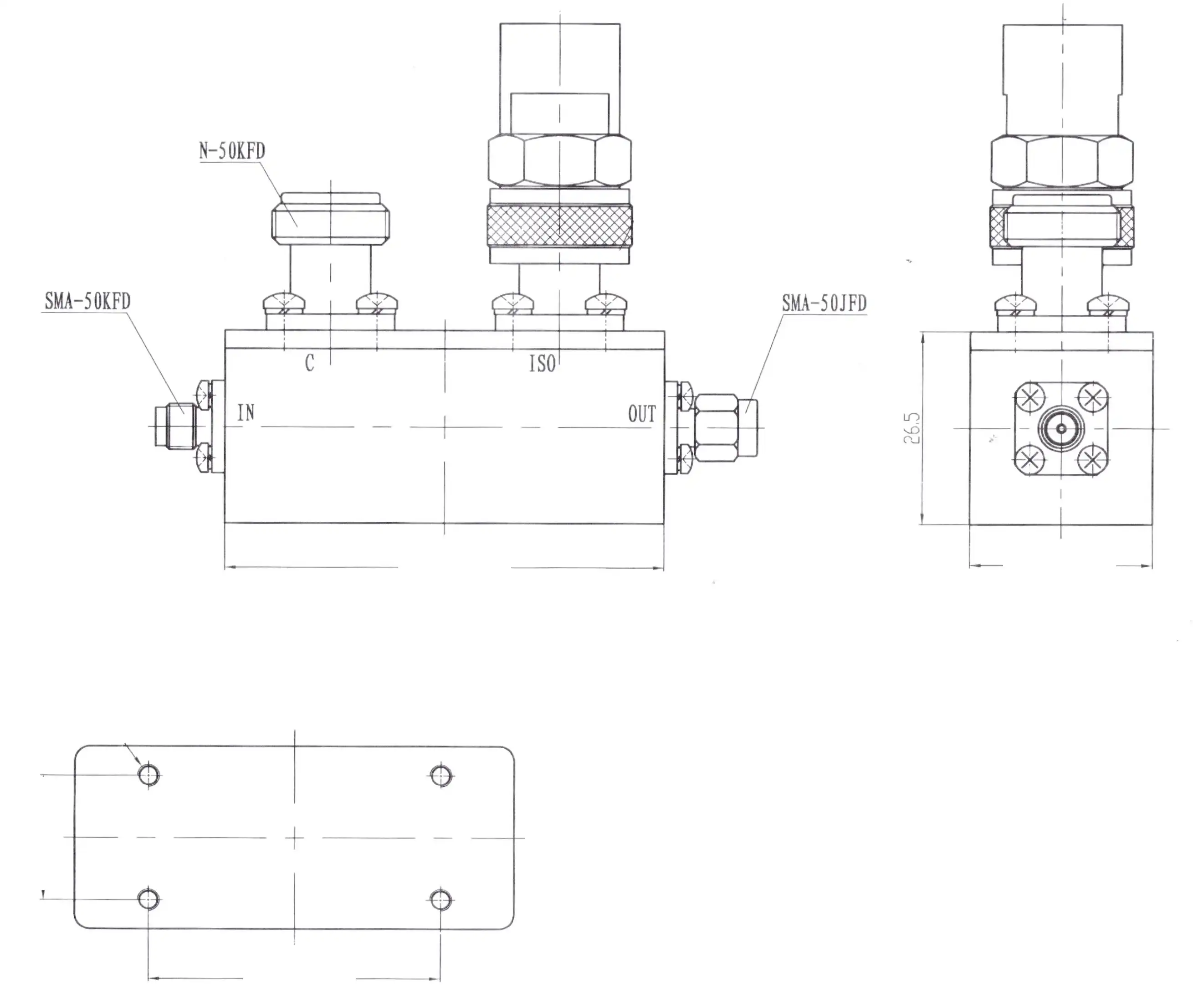
A dual-directional coupler adds a second coupled port inside the same housing that picks up waves going in the opposite way. In other words, you can use a single inline device to measure both forward and reflected power at the same time. The dual design gets rid of the need for two different units and the phase uncertainty that comes with cascading them. This is useful for tracking antenna VSWR, setting up reflectometers, and any other task that needs real-time impedance health checks.
How to Choose Based on Your Test Requirements
What you need to measure and how often you need to measure both ways at the same time will help you decide. This is a useful way to think about the choice:
- Choose single when your test needs forward power sampling or one-directional signal monitoring, and budget or board space is a constraint.
- Choose dual when your test requires simultaneous forward and reflected wave data — particularly for return loss, VSWR measurement, or ALC feedback requiring bi-directional awareness.
- Consider frequency range and connector type regardless of configuration. An N-type coupler rated to 18 GHz behaves very differently from an SMA unit optimized for a specific narrowband.
These standards are used for buying defense electronics, checking satellite links, and doing RF testing on the production line. The dual unit's higher price is often justified by how well it does tests.
Market Comparison: Leading Coaxial Directional Coupler Options for B2B Buyers
When buying RF couplers, procurement teams usually look at a number of well-known names as well as smaller, more specialized makers.
Major Brands and Their Focus Areas
Mini-Circuits is known for having a large collection and reasonable prices on standard models, which makes them a good choice for buying in bulk. Keysight Technologies makes couplers that work well with VNA systems and are the best at precision measurement applications. Pasternack has a huge range of link types and frequency bands, which is useful for meeting quick-sourcing needs.
What ADM Brings to the Table
Advanced Microwave Technologies Co., Ltd. (ADM) is different because it has been making things for over 20 years and can test them in-house up to 110 GHz. The RF coaxial directional couplers made by ADM are certified to ISO 9001:2015 and do not contain any harmful substances. This means they meet the standards for traceability and paperwork that are popular in military and aerospace procurement. ADM also lets OEMs make changes to the connector type, coupling factor, housing material, and frequency band so that they meet your exact integration needs. You can get a prototype quickly and look it over before committing to full production.
Procurement Logistics to Keep in Mind
Lead times and minimum order quantities are very different between suppliers. ADM can handle both small orders for prototypes and large-scale production. They have engineers who can help with technical issues directly, and they know what needs to be done in satellite communication, radar, and industry R&D settings.
How to Integrate Your RF Coupler into Existing Test Setups
Getting the part right is only half the job; how it is installed also has a big impact on how well it works.
Matching Specs to Your System
Check to see if the coupler's frequency range covers your whole working band, including any harmonics you might be trying. A unit with a rating of 0.5 GHz to 18 GHz works well in X-band radar test setups. On the other hand, Ku-band satellite ground station uses may need a range up to or exceeding 18 GHz. Before placing an order, you should always make sure that the connectors will work together. Using SMA and N-type together without the right adapters can cause readings to be off because they add extra reflection points.
Minimizing Insertion Loss and VSWR on Installation
Make sure the wire runs between the coupler and your DUT are short and tightened up to the manufacturer's specs. An SMA connector that is just a little bit loose can add 0.1 dB to 0.3 dB of unwanted insertion loss, which builds up along a test chain. When you connect to coupler ports on high-precision benches, use precision torque wrenches.
Troubleshooting Unexpected Performance Variations
Most of the time, a bad connector contact or a broken center pin is to blame when directivity numbers are lower than expected. Mismatched terminations on unused ports cause reflections that lower directivity as well. Always use a well-matched 50-ohm load to terminate empty ports.
Future-Proofing Your Procurement: Trends in RF Coupler Design
The market for directional couplers is shifting toward smaller units that can handle a wider range of frequencies. In 5G mmWave assemblies, smaller surface-mount couplers are becoming more popular. On the other hand, coaxial form factors are still the most common choice for defense and satellite uses that need to handle a lot of power and last a long time. System designers who need to be flexible across multiple projects without having to rethink their test interfaces are starting to use modular coupler kits with connector flanges that can be switched out. For long-term planning of purchases, give top priority to suppliers who offer documented calibration data, engineering support after the sale, and the manufacturing flexibility to accommodate changes to the design without having to go through long re-qualification processes.
Conclusion
It's not a small thing to choose between a single- and dual-directional coaxial directional coupler; it affects the quality of every measurement your test setup makes. Focused, one-directional tracking works well with single setups, while more complicated test scenarios need dual configurations that can measure both forward and reflected power at the same time. Your RF chain will work as it should if you make sure that the choice you make fits with the actual test needs, the system frequency bands, and the connector infrastructure. Both of these setups are available in ADM's product line, and the company offers customization options and ready-to-use approval documents to help with the buying process in defense, satellite, and industrial settings.
FAQ
What is the typical directivity specification for a quality RF directional coupler?
Most well-engineered directional couplers specify directivity greater than 20 dB, with high-performance units exceeding 30 dB. Higher directivity means the coupler more accurately separates forward and reflected signals, which directly improves return loss measurement accuracy. For VNA applications and antenna testing, a minimum of 25 dB directivity is generally recommended.
Can a single directional coupler replace a dual unit in a reflectometer setup?
Not without adding a second coupler. A reflectometer requires simultaneous sampling of both forward and reflected waves. A single unit captures only one direction, so two would need to be cascaded — introducing phase and alignment variables that a dual configuration avoids by design.
What connector types are commonly available on coaxial directional couplers?
Standard connector options include SMA, N-type, TNC, and 2.92 mm (K-type) for higher frequency applications. Connector choice depends on frequency range, power level, and mating interface compatibility with your existing test equipment.
How does coupling factor selection affect measurement sensitivity?
A higher coupling factor (e.g., 40 dB) draws less power from the main line but requires a more sensitive detector at the coupled port. A lower coupling factor (e.g., 10 dB) provides a stronger signal at the coupled port but slightly increases main-line loading. Match the coupling factor to your detector's dynamic range.
Partner With ADM for Your Next RF Coupler Requirement
Precision coaxial directional couplers made for defense, satellite, and industrial test environments are made and sold by ADM. ADM is a coaxial directional coupler maker you can trust for both standard and application-specific designs. They are ISO 9001:2015 certified, test their products in-house up to 110 GHz, and offer OEM customization from pilot to mass production. Get in touch with ADM's tech team at craig@admicrowave.com to talk about your unique needs.
References
1. Pozar, D. M. Microwave Engineering, 4th ed. — John Wiley & Sons, 2011.
2. Matthaei, G., Young, L., & Jones, E. M. T. Microwave Filters, Impedance-Matching Networks, and Coupling Structures — Artech House, 1980.
3. Mini-Circuits. Application Note: Understanding Directional Couplers — Mini-Circuits Technical Library, 2019.
4. Keysight Technologies. RF Component Measurement Solutions: Coupler Performance Verification — Keysight Application Note 5990-9783EN, 2020.
5. Montgomery, C. G., Dicke, R. H., & Purcell, E. M. Principles of Microwave Circuits — MIT Radiation Laboratory Series, McGraw-Hill, 1948.
6. IEEE Std 686-2008. IEEE Standard Radar Definitions — Institute of Electrical and Electronics Engineers, 2008.