





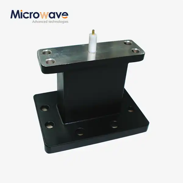
End Launch Waveguide to Microstrip Adapter
End Launch Waveguide to Microstrip Adapter — Precision TE10 to Quasi-TEM Transition for mmWave Systems
The End Launch Waveguide to Microstrip Adapter is an electromechanical transition component that bridges a rectangular metallic waveguide operating in TE10 mode and a planar microstrip transmission line in Quasi-TEM mode on a PCB. Unlike right-angle designs, the end-launch configuration supports inline, axial connection — making it well suited for compact millimeter-wave module integration across Ka, V, E, and W-band hybrid RF systems from 26.5 GHz to 110 GHz.
What Is an End Launch Waveguide to Microstrip Adapter?
This component addresses one of the more persistent challenges in high-frequency design: moving a signal from a 3D air-dielectric waveguide into a 2D planar circuit without degrading signal integrity.
The waveguide carries electromagnetic energy in TE10 mode. The PCB microstrip operates in Quasi-TEM mode. These are fundamentally different transmission environments. The adapter converts between them with minimal loss by using a precision launch pin that couples the electromagnetic field directly onto the PCB substrate, maintaining 50-ohm broadband impedance matching throughout the transition.
The machined body — typically brass or aluminum — is gold or silver plated to reduce skin-effect losses at millimeter-wave frequencies.
Key Technical Specifications
Parameter | Typical Value |
Frequency Range | 26.5 GHz – 110 GHz (component dependent) |
VSWR | < 1.3:1 (< 1.5:1 at band edges) |
Insertion Loss | < 0.35 dB |
Impedance | 50 Ohms |
Waveguide Flange Standard | MIL-DTL-3922 / UG-series (e.g., UG-387/U for WR-15) |
Body Material | Brass or aluminum, precision machined |
Plating | Gold or silver |
Operating Temperature | -55°C to +125°C |
Core Technical Features
Inline End-Launch Configuration
The End Launch Waveguide to Microstrip Adapter's axial link design lets it be directly built into small millimeter-wave modules without the signal path bends that come with right-angle designs.
Broadband 50-Ohm Impedance Matching
The launch pin geometry is designed to keep the impedance the same across the operating band. This keeps the VSWR below 1.3:1 for most of the operating band.
Precision Machined Body with Plating
The bodies are made of brass or aluminium and are machined to very close tolerances. They are then gold or silver-plated to lower the resistance of the surface and protect it from corrosion in the field.
Choice of Hermetic Sealing
For situations where moisture or hoover exposure is a problem, like outdoor telecom equipment or space-based payloads, there are hermetic sealing configurations that can be used.
Suppression of Higher-Order Modes
Higher-order modes are stopped by a backshort cavity mixed with choke structures or a tapered launch pin geometry. This makes sure that the Quasi-TEM signal can travel cleanly onto the microstrip line.
Application Scenarios
5G/6G mmWave Backhaul Systems
For high-capacity backhaul links, these adapters keep the signal strong across an outdoor waveguide antenna to an indoor digital processing board. This is necessary because the interface is open to the weather.
Automotive Radar Transceivers (77 GHz)
The adapter links MMIC radar chips on the PCB to horn antennas or slotted waveguide arrays in systems that try to avoid collisions. How well a target is found depends directly on how well this transition works.
Satellite Communication (SATCOM) Payloads
LEO satellite designs need to be as small and light as possible. These adapters have high-power waveguide amplifiers and planar control circuits built in. They can work in a vacuum and can handle temperature changes of -55°C to +125°C.
Quality Control Process
ADM checks the quality of waveguide-to-microstrip transitions for both electromagnetic performance and mechanical accuracy.
Checking of S-Parameters
To make sure there aren't any resonance spikes in the operating band, Vector Network Analysers (VNA) check S11 and S21 across the whole frequency range.
Dimensional Accuracy and Pin Alignment
Coordinate Measuring Machines (CMM) check the depth and centring of the launch pins in relation to the waveguide opening. Misalignment on the micron scale is enough to hurt VSWR performance at W-band frequencies.
Check for Plating Integrity
X-ray fluorescence (XRF) testing checks the thickness of gold or silver plating to make sure it meets requirements for conductivity and corrosion resistance.
Thermal Cycle Testing
Temperature cycling from -55°C to +125°C is used to make sure that the CTE mismatch between the metal body and PCB dielectric contact doesn't lead to mechanical failure over time.
PCB Integration Considerations
Selecting the right End Launch Waveguide to Microstrip Adapter requires matching it to your specific PCB design. The transition probe geometry must be matched to your substrate's dielectric constant and thickness. Rogers RO3003 and RO4350B, for example, behave differently at millimeter-wave frequencies, and a mismatched probe introduces capacitive discontinuities that degrade insertion loss and VSWR.
Your PCB layout needs a defined footprint for the mounting screws and the signal launch landing pad on the microstrip side, alongside the standard UG-series flange pattern on the waveguide side.
Power handling is also a design consideration. The waveguide body can handle kilowatts, but the microstrip transition point limits CW power to tens of watts, depending on track width and heat sinking. Exceeding this threshold risks dielectric breakdown or track delamination.
ADM Testing and Manufacturing Capability
ADM operates a 24-meter Microwave Darkroom for high-precision antenna and component testing. Coverage spans 0.5 GHz to 110 GHz, supporting full characterization of millimeter-wave products including waveguide transitions. The facility supports near-field and far-field measurement switching through an Antenna Plane Near and Far Field Measuring Recombination Chamber.
ADM's engineering team supports both custom transition designs and standard catalog configurations for customers in aerospace, satellite communication, and advanced wireless systems.
FAQ
Q: How does the thickness of the substrate affect how well an adapter works?
A: The shape of the probe needs to match the dielectric constant and thickness of your PCB. If you use a probe made for RO3003 on a RO4350B, for example, capacitive discontinuities and higher insertion loss will happen. Before choosing a configuration, give ADM's engineering team information about your substrate.
Q: What limits how much power can be handled at the changeover point?
A: The microstrip transition is what limits the power in the waveguide section, which can handle kilowatts. When it comes to track width and heat loss, CW power is usually limited to tens of watts. If you go over this, the dielectric could break down or the track could delaminate.
Q: Is there a standard way that waveguide flanges should be arranged?
A: Yes. As required by MIL-DTL-3922, the waveguide side has standard UG-series flange patterns, such as UG-387/U for WR-15. For attaching screws and the signal launch pad, the PCB side needs a certain footprint.
Q: How do you turn off higher-order modes?
A: A precise backshort cavity along with choke structures or a tapered launch pin stops higher-order modes and makes sure that the Quasi-TEM signal moves smoothly onto the microstrip.
Q: Does the center wire contact need to be soldered?
Answer: It varies on the use. When reusability is important, clam-shell compression contacts are good for testing and assessment. Permanent, high-vibration installations of flight-grade hardware are usually done by soldering or wire bonding.
Q: What kind of custom waveguide band and substrate configurations does ADM support?
A: Yes. The engineering team at ADM can make unique transition designs that fit your waveguide band, PCB substrate, and frequency of operation. For a technical review of your application, get in touch with the team.
Contact Us
Have a custom configuration or technical question about the End Launch Waveguide to Microstrip Adapter? Reach ADM's engineering team at craig@admicrowave.com with your waveguide band, substrate type, and frequency range.
YOU MAY LIKE
 VIEW MOREHigh Power Waveguide to Coaxial Adapter
 VIEW MOREEnd Launch Waveguide to Coaxial Adapter
 VIEW MORERight Angle Waveguide To Coaxial Adapter
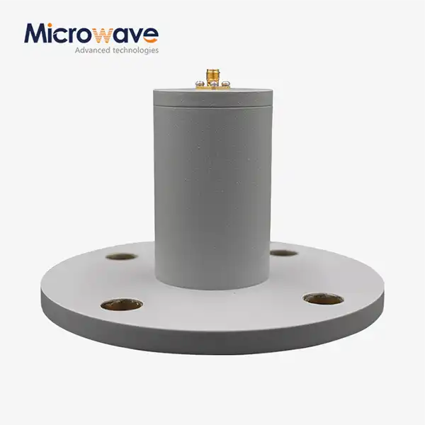 VIEW MORECircular Waveguide To Coaxial Adapter
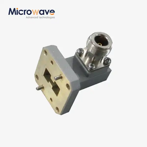 VIEW MORERight Angle Double Ridged WG To Coaxial Adapter
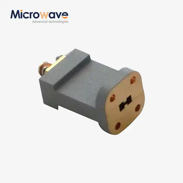 VIEW MOREEnd Launch Double Ridged WG To Coaxial Adapter
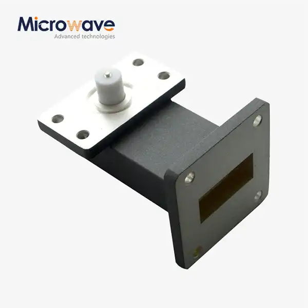 VIEW MORERight Angle Waveguide to Microstrip Adapter
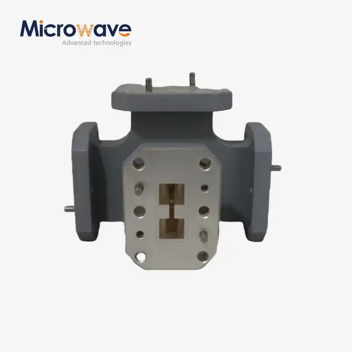 VIEW MOREDouble-Ridged Waveguide Magic Tee
