





Twisted Waveguide Design: Principles, Benefits, and Applications
A twisted waveguide incorporates a gradual rotational transformation along its transmission path, enabling microwave systems to navigate complex spatial geometries while maintaining exceptional signal fidelity. This specialized component solves critical routing challenges in satellite feeds, radar assemblies, and aerospace platforms where physical constraints demand both mechanical flexibility and electrical precision. By introducing controlled geometric rotation, twisted waveguides preserve mode purity and minimize reflection losses that would otherwise compromise system performance in high-frequency applications.
Understanding Twisted Waveguide Design and Working Principles
Because of its purposeful rotational shape, a twisted waveguide is different from regular communication lines. In contrast to regular rectangular waveguides, which have a fixed cross-sectional orientation, this design adds a continuous angular displacement along the longitudinal axis.
How Geometric Rotation Affects Wave Propagation
The electromagnetic field inside a twisted waveguide changes its polarization slowly as it moves through the turned structure. This controlled rotation lets the main TE10 mode stay coherent even when the mounting direction changes by an angle. Twist rates, which are usually given in degrees per meter, are chosen by engineers based on the frequency of operation and the amount of mechanical flexibility that is needed. How smoothly energy moves along the path of rotation is based on the relationship between twist angle and wavelength.
Choosing the right materials is also very important for how well they work. Because they are so good at conducting electricity and being machined, brass and copper alloys are used a lot in manufacturing. The finish on the inside of the part directly affects insertion loss. For low resistive losses at millimeter-wave frequencies, precise machining techniques make the surface roughness greater than 1.6 micrometers. We use convoluted construction with helically wound strips for uses that need more flexibility. This lets the material bend while keeping its twisting shape.
Critical Design Parameters for System Integration
The manufacturing tolerances get tighter as the operating frequency goes up. At X-band frequencies (8–12 GHz), differences in size of no more than ±0.05 mm ensure good VSWR performance. For millimeter-wave uses, controls need to be even tighter, and tolerance stacks need to be below ±0.02mm to keep insertion loss standards and stop mode conversion. Depending on the impedance matching needs, the twist profile has to follow exact mathematical functions. These can be linear, exponential, or special shapes.
Power handling capacity is based on how cross-sectional dimensions and twist rate work together. Our twistable, flexible waveguides find the best balance between mechanical flexibility and electrical performance by finding the best wall thickness and corrugation depth. Our basic models come with a Neoprene jacket that seals them against pressure and protects them from the environment without changing their RF properties. This is especially important for outdoor setups and mobile platforms.
Key Benefits and Advantages of Twisted Waveguides
When rigid waveguides can't be installed because of installation problems, system architects are choosing twisted waveguides more and more. When rotary power and transmission efficiency are combined, performance is improved in a number of ways that can be measured.
Operational Advantages in Complex Assemblies
In the real world, integration problems happen when installing radio feeds and putting together radar subsystems. These specialized parts solve those problems. When mounting flanges need an angle difference between the transmitter outputs and antenna inputs, the usual way to do it is to use several stiff bends with reflections at each point. These breaks are taken out by a single twisted section, which lowers the total insertion loss by 0.3 to 0.8 dB, depending on the frequency band and total rotation angle.
Another important benefit is the maintenance of mode purity. In normal waveguide routes, sudden bends can set off higher-order modes that hurt pattern symmetry and cross-polarization performance. Because twisted designs rotate slowly, the field distribution stays the same. This keeps the generation of unwanted modes below -40 dB compared to the dominant mode over operational bandwidths of 40% or more.
In places where vibrations are common, systems that can relieve mechanical stress last longer. Continuous mechanical excitation can wear out rigid waveguide joints in aircraft radar installations and shipboard communication systems. Our waveguides are bendable and can be twisted. They absorb vibration energy by controlled bending, which keeps cracks from starting at flange surfaces and solder joints. Tests show that it will work reliably for 10 million flex cycles at normal aviation vibration levels.
When RF elements are packed closely together, the benefits of optimizing space become clear. Designers of satellite payloads like how bending and turning can be combined in one part to make the route smaller. When compared to rigid-only implementations, this feature cuts the overall assembly volume by 15–30%. This directly leads to mass savings in applications that are important for launch.
According to feedback from aerospace OEM partners, these benefits make the system more reliable and make installation easier. This cuts the time it takes to integrate by up to 40%. Being able to deal with differences in as-built dimensions without having to make new parts speeds up projects and lowers the overall cost of buying.
Common Applications of Twisted Waveguides in Industry
Twisted waveguide technology allows solutions in mission-critical industries that would be impossible or impractical with traditional transmission line methods.
Satellite Ground Stations and Space Communications
Twisted sections are often used in earth station antenna feeds to change between feed horn polarization and waveguide route direction. Our products work with installations from L-band to Ka-band (1-40 GHz), which covers the wide frequency ranges needed for telemetry, tracking, and command operations to happen at the same time. The low insertion loss—usually between 0.15 and 0.40 dB/meter depending on frequency—protects the link cushion in situations where power is limited and every tenth of a decibel changes the amount of data that can be sent.
Designers of satellite payloads use our flexible twisted waveguides to connect transponder outputs to movable reflector feeds. Once the reflector is in orbit, the mechanical contact shape changes. The parts keep the VSWR below 1.15:1 across all operating bands, which makes sure that power transfer works well for mission lives of more than 15 years.
Aerospace Radar and Navigation Systems
Twisted waveguides are used in gimbal-mounted antenna arrays for airborne weather radar systems where continuous angular scanning requires rotary freedom. Our designs can handle peak power levels above 10 kW and twisting angles of up to 350 degrees per meter, meeting the strict requirements of commercial aviation safety systems. We make double-ridged configurations that increase bandwidth for multi-mode radar applications that need to map terrain and find weather at the same time.
When military surveillance platforms use electronically scanned array feeds, they include twisted sections. To get from T/R modules to radiating elements, the feeds have to go through complicated three-dimensional paths in a small fuselage volume. Precision phase stability of better than ±3 degrees across temperature ranges from -55°C to +85°C keeps beam aiming accurate, which is important for tracking targets.
Telecommunications Infrastructure and 5G Networks
As deployment moves to roofs and other non-traditional sites with tricky entry geometries, base station installations depend more and more on flexible transmission options. Our products make it easy for field workers to quickly install them without needing to know how to tune the RF signals. This cuts the time it takes to set up a spot from hours to minutes. The large bandwidth support lets multiple bands work together, which lets operators combine their infrastructure as spectrum allocations change.
Laboratory Test Equipment and Research Instrumentation
For testing electromagnetic compatibility and characterizing antennas, research facilities use twisted waveguides in measurement setups that need to be reconfigured often. Electrical performance can be repeated after mechanical adjustment, usually within 0.05 dB and 2 degrees. This makes sure that measurements are the same from one experiment to the next. Our parts work reliably in the controlled environment of anechoic rooms and can also handle the handling and changing temperatures that come with field test missions.
Comparing and Selecting the Right Twisted Waveguide for Your Needs
When selecting twisted waveguides for system integration, procurement teams have to make a number of choices. Knowing the technical trade-offs and what the provider can do makes the decision process go more quickly.
Performance Metrics That Matter
It is important to choose a device based on its insertion loss because it has a direct effect on the system noise figure and output power. Instead of single-point values, our specification tables show measured data across full waveguide bands. This lets you do exact link budget estimates. In the 8.2-12.4 GHz range, the ADM-100WEL series achieves ≤0.40 dB/m and a maximum twist capability of 240 degrees/meter. These specs have been confirmed by measurements taken with a network analyzer that can be traced back to NIST standards.
Specifications for VSWR show how well impedance matching works. When the value is less than 1.15:1, the reflected power stays below 0.3%, which is fine for most emitter safety circuits. Higher-performance uses, like particle accelerator RF systems, may need VSWR below 1.10:1. Our ADM-40WEL through ADM-58WEL product lines offer this for lower frequency bands where better matching is easier due to smaller gaps.
Routing design is limited by the minimum bend radius. Our specs list different values for E-plane and H-plane bending—102mm and 204mm for the ADM-70WEL model, respectively—which shows how rectangular cross-sections aren't always flexible in the same way. During mechanical design, system layouts must take these limitations into account so that stress levels don't go over limits that would hurt electrical performance or cause failure before they're supposed to.
Supplier Evaluation and Partnership Considerations
Besides looking at the specs of the parts, procurement managers also look at the skills of the suppliers that could affect the success of the project. Lead times depend on how much can be made, especially for custom frequency bands or twist shapes that aren't common. Advanced Microwave Technologies has dedicated production lines for making flexible waveguides. This means that custom configurations can be delivered in 4 to 6 weeks, compared to 12 to 16 weeks for suppliers who use outside subcontractors.
The level of technical support is what sets true partners apart from commodity vendors. Our applications engineering team makes computer models that work with both CST and HFSS electromagnetic solvers. This speeds up the design testing process for our customers. Before committing to tools, pre-production design reviews find any possible interface problems. This lowers the risk of having to make expensive redesigns during system readiness testing.
The end market sets different standards for quality documents. Defense and aircraft projects need a lot of information to be able to track down products, like material certifications, dimensional inspection reports, and test data from a network analyzer for each serial number. Our methods, which are ISO 9001:2015 certified, make this paperwork as normal, and they also keep the RoHS compliance records that are needed for export markets.
How to Buy Twisted Waveguides: A Practical Guide for Procurement Managers
For a procurement to go well, there must be clear technical needs that come from system-level specs and integration constraints.
Defining Requirements and Engaging Suppliers
Start by writing down the operating frequency range, leaving room for future growth. Instead of accepting catalog specifications that might be higher than what is needed, set the limits for VSWR and insertion loss based on a link budget analysis. This could save money. Include the temperature range, humidity exposure, and vibration profiles of the environment that affect the choice of material and the specifications for the protective jacket.
Mechanical interface features keep expensive mistakes from happening. Give the types of flanges (CPR, UG, or custom), along with any revision levels that may be needed, since small changes in dimensions between revisions can affect how well they fit together. Include the total length that needs to be installed and the angle of spin that needs to be allowed, along with any tolerance bands that need to be used to account for differences in the actual installation.
When we involve our expert team early on, things go better. During the proposal phase, design discussions find ways to make things better, like switching to standard flange types that make delivery better or offering different frequency bands that provide better electrical performance. Most of the time, these talks happen via email at craig@admicrowave.com. Within one business day, our application experts reply with initial suggestions.
Prototyping, Testing, and Production Transitions
Ask for a certain number of prototypes to be tested for quality before committing to production volumes. We usually send out two to three evaluation units within three to four weeks. This gives customers time to test the electrical performance in real system configurations and make sure the mechanical fit is correct. This investment, which is usually 10–15 percent of the total cost of all the program's parts, greatly lowers the chance that design errors will be found during system integration.
Sample testing should be done in the same way that it will be used in the end. Check the insertion loss and VSWR over the whole temperature range, do flex cycling if the system needs to be moved around a lot, and make sure the power handling works at the highest predicted transmitter output. Write down the results in qualification reports that are added to the procurement record. These reports set the standard for performance for production acceptance criteria.
Clear acceptance criteria that come from testing prototypes are helpful for production orders. Choose sampling plans (100% test, random sampling, or first-article inspection) that are right for the amount and criticality of the application. As a standard, we use a network monitor to check every unit for insertion loss, VSWR, and phase tracking. Data packages are sent with orders so that customers can check them when they get them.
Conclusion
Twisted waveguide technology solves some of the most important problems in integrating current RF systems, where electrical performance standards are very high and mechanical complexity is high. The controlled rotational geometry makes it possible for small routing solutions to be used while keeping the signal integrity at frequencies from the L-band to millimeter waves. These specialized parts are needed for a wide range of applications, from satellite ground stations to aircraft radar platforms, to work reliably in harsh conditions. To be successful with selection, you need to know the trade-offs between performance, be clear about what you need, and work with makers who have both scientific depth and production capability. As wireless infrastructure and aerospace systems move toward higher frequencies and smaller packages, flexible twisted waveguides play an increasingly important role in making next-generation designs possible.
FAQ
What distinguishes a twisted waveguide from standard flexible waveguides?
Standard flexible waveguides can bend in one or both directions while keeping their shape across the cross-section. Twisted waveguides let you control movement along the lengthwise axis, which lets you set the angle between the input and output flanges. This extra degree of freedom makes installation easier in situations where mounting interfaces aren't lined up correctly rotationally. It gets rid of the need for multiple bends or mechanical adapters that would make insertion loss and reflection worse.
Can twisted waveguides handle high-power applications?
Yes, twisted waveguides can carry high power levels that are similar to rigid options when they are properly designed. How much power is handled varies with the frequency, the cross-sectional size, and the cooling system. Our X-band models can safely handle peak power of more than 10 kW and constant power of more than 1 kW, which is enough for most radar and communication devices. Specific power ratings depend on the model and the environment. For help with your specific application, please contact our engineering team.
How does customization affect delivery schedules?
Standard stock setups are sent out 4 to 6 weeks after the order is confirmed. Custom specifications with non-standard frequencies, special flange types, or unique twist profiles make delivery take 6 to 8 weeks longer because the tools need to be prepared and tested to make sure they are qualified. Usually, prototypes ship faster—in about three to four weeks—so that the design can be checked while the production tools are being made. We can make sure that the manufacturing schedules are in line with the project goals if we get involved early in the planning phase.
Partner with ADM for Your Twisted Waveguide Requirements
With more than 20 years of experience making specialized products, Advanced Microwave Technologies is ready to help you buy microwave parts. As a reliable twisted waveguide provider, we offer precisely designed flexible twistable waveguides with a frequency range of 3.22 to 50.1 GHz. Each one comes with full test data and ISO 9001 certification. We can customize non-standard twist rates, special jacket materials, and frequency bands that aren't in our catalog. During the whole design process, we'll be there to help you with engineering questions. Because our processes are streamlined, we can deliver quality parts on time, whether your application needs a sample to be tested or a lot of them to be made. Email our technical team at craig@admicrowave.com to talk about your particular needs, get full specs, or set up an evaluation sample. We offer the technical support and high-quality manufacturing that turn tough RF integration problems into successful system deployments.
References
1. Pozar, David M. Microwave Engineering, 4th Edition. Wiley, 2011.
2. Marcuvitz, Nathan. Waveguide Handbook. Institution of Engineering and Technology, 1986.
3. Saad, Theodore S. Microwave Engineers' Handbook, Volume 1. Artech House, 1971.
4. Clarricoats, P.J.B., and A.D. Olver. Corrugated Horns for Microwave Antennas. Peter Peregrinus Ltd., 1984.
5. Uher, Jiri, Jens Bornemann, and Uwe Rosenberg. Waveguide Components for Antenna Feed Systems: Theory and CAD. Artech House, 1993.
6. Balanis, Constantine A. Advanced Engineering Electromagnetics, 2nd Edition. Wiley, 2012.
YOU MAY LIKE
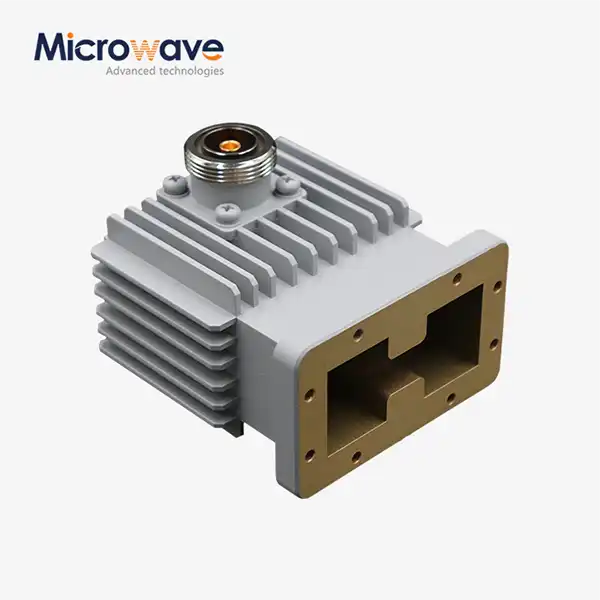 VIEW MOREHigh Power Waveguide to Coaxial Adapter
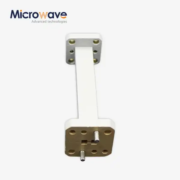 VIEW MOREWaveguide Straights and Transitions
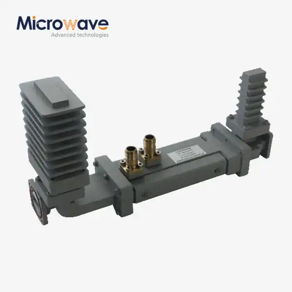 VIEW MOREHigh Power Waveguide Differential Phase Shift Isolator
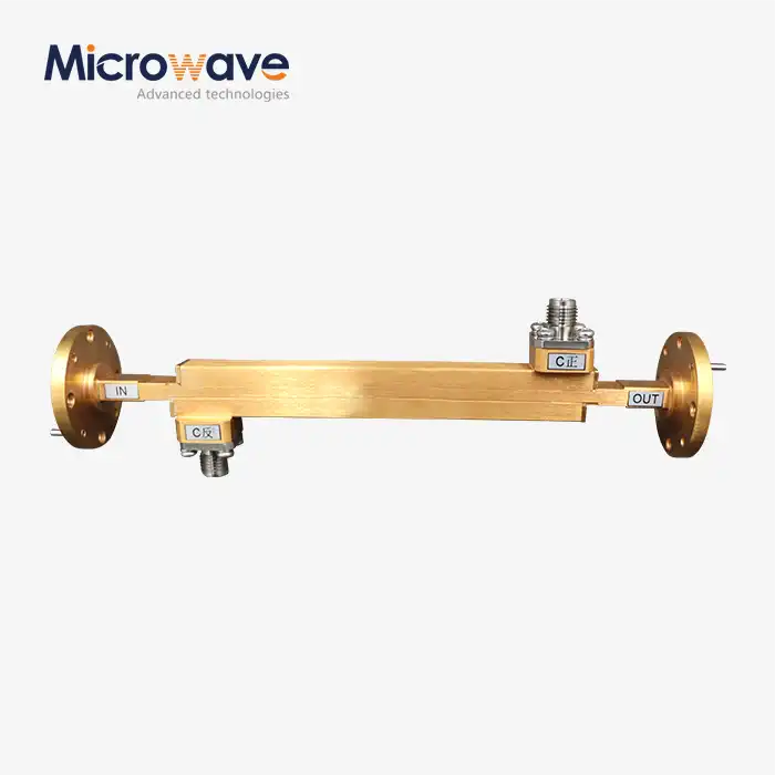 VIEW MOREDouble-Ridged Waveguide Broadwall Directional Coupler
 VIEW MORECoaxial Load
 VIEW MOREFeed Fired Lens Antenna
 VIEW MOREMini Wideband Double-ridged Horn Antenna
 VIEW MOREOpen Boundary Dual Linear Polarization Four Ridged Horn Antenna
