





Pyramidal Horn Antenna Design: A Practical Guide
Pyramidal horn antenna design represents a critical engineering discipline for professionals working in microwave and RF systems. This practical guide addresses the essential principles behind designing these antennas, focusing on flare geometry, aperture calculations, and impedance matching strategies. Whether you're optimizing for satellite ground stations, radar feeds, or EMC testing applications, understanding the relationship between physical dimensions and electromagnetic performance ensures your antenna delivers predictable gain, controlled beam patterns, and minimal signal reflection across your target frequency range.
Understanding Pyramidal Horn Antenna Design Principles
Pyramidal horn antennas change the impedance very precisely, going from the limited shape of rectangular waveguides to the 377-ohm impedance of empty space. This controlled growth lowers the voltage standing wave ratio (VSWR) and raises the efficiency of power transfer, which is very important when working with sensitive measurement equipment or high-power radar emitters.
Core Structural Parameters
The design begins with three basic measurements that describe how the antenna works. The effective radiating area is based on the aperture dimensions in both the E-plane (electric field plane) and the H-plane (magnetic field plane). The phase mistake across the lens opening is controlled by the flare length. The flare angle determines how fast the waveguide expands, which has a direct effect on the quality of the impedance matching. The characteristics of the radiation and the operational bandwidth are shaped by these parameters working together.
We figure out the aperture size for each application by using the working frequency and the gain that is needed. It takes longer for flare lengths to stay the same length when the aperture is bigger, but the directivity is higher. The best curve length is usually between 0.5λ and 3λ at the center frequency, taking into account both performance needs and size limitations.
Radiation Pattern and Gain Calculations
Radiation patterns show up when the field is spread out across the opening. Because the apertures are different sizes, the E-plane design usually has a smaller beamwidth than the H-plane. To figure out the gain, use the standard aperture antenna formula: 10 log₁₀(4π × Ae / λ²), where Ae is the effective aperture area, and λ is the wavelength.
To get a high aperture efficiency (the ratio of the effective aperture to the physical aperture), the flare geometry needs to cause as few phase errors as possible. When the flare angle gets too high, the wavefront curves at the aperture plane, which makes the phase error worse. Standard designs in the industry keep phase error below 45 degrees across the opening to keep the beam quality and gain.
Impedance Matching and Feed Design
The area where the waveguide meets the horn is where the impedance matching network is located. Unexpected changes cause reflections that lower VSWR and add ripples to the frequency response. Gradual flare patterns spread the impedance change over a larger area, lowering the reflection coefficients to a safe level, usually VSWR below 1.5:1 across the working band.
There are more things to think about when designing a feed than just attaching a waveguide. Throughout the desired bandwidth, the connecting waveguide size must operate above its cutoff frequency. To keep the electricity flowing and stop RF leakage, flange connections need to be torqued to the right specs. Tolerances for precision machining have a direct effect on high-frequency performance, especially above 18 GHz, where surface roughness and dimensional accuracy become more important.
Comparing Pyramidal Horn Antennas with Other Antenna Types
When purchasing antenna solutions, it's helpful for teams to know how Pyramidal horn antennas stack up against other designs in terms of different performance measures and application needs.
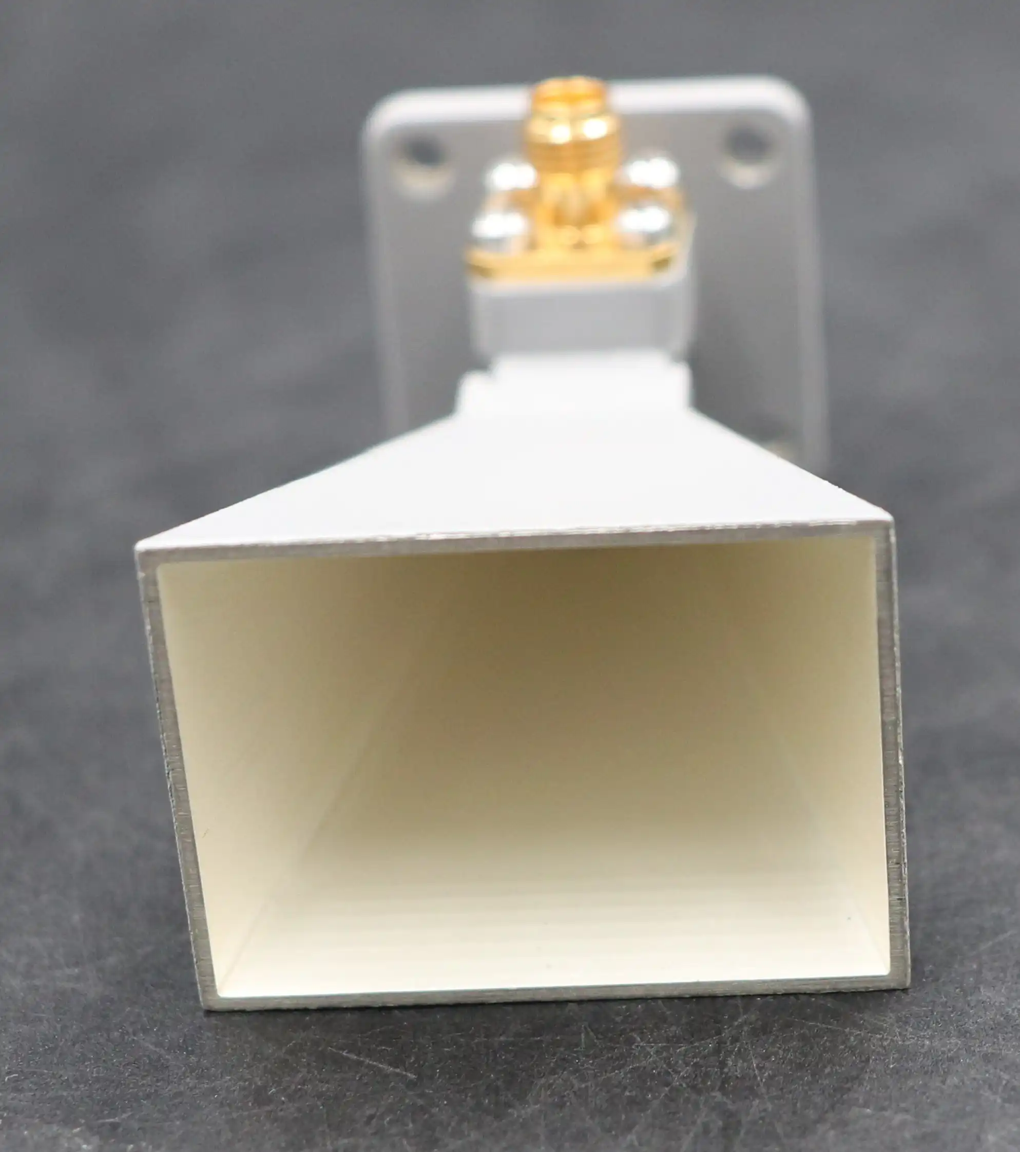
Structural and Performance Distinctions
Conical horn antennas change from circular waveguides to make shapes that are symmetric around a circle. Even tho they are easier to build mechanically, they don't have the same level of polarization clarity as pyramidal forms. When compared to well-designed Pyramidal horn antennas, conical horns usually have 3–5 dB less cross-polarization isolation. This makes them less useful for applications that need tight control over polarization.
Sectoral horn antennas only spread in one direction, either in the E-plane or the H-plane. These designs make fan-shaped beams that can be used in cell phone base stations or airport surveillance radar for specific coverage patterns. But their gain is still a lot less than that of Pyramidal horn antennas with the same opening size. Sectoral horns are useful when covering a large area in one plane is more important than being able to focus the beam perfectly.
Open-ended waveguides are the simplest way to radiate, but they don't match impedances well and have low gain. The sudden end causes a lot of reflections, which limits the bandwidth that can be used and the amount of power that can be handled. Adding the pyramidal flare structure gets rid of these basic problems, which is why horn antennas are used in most high-performance transmission and accurate measurement systems.
Traditional Versus Compact Design Trade-offs
Standard pyramidal horn antenna designs focus on getting the most gain and pattern clarity, which makes the structures longer. In places with little to no space, like labs, antenna test ranges, and ground-based satellite terminals, these traditional configurations work very well. Their longer flare length makes sure that the phase is well-coordinated across the lens.
Some versions of the compact Pyramidal horn antenna give up some ability in exchange for being smaller and lighter. This is done by designers using dielectric loading techniques or steeper flare angles that are steeper. In exchange, you have to be willing to live with slightly worse VSWR, less bandwidth, or higher side-lobe levels. Small designs are useful for situations where integrating platforms is hard, like in airborne radar pods or mobile communication terminals, where small performance losses are acceptable.
When making procurement choices, cost is a very important issue. For most commercial uses, precision-machined metal Pyramidal horn antennas that work below 18 GHz are a cost-effective option. Designs with higher frequencies needing tighter tolerances or unusual materials like gold-plated copper make production more difficult and cost more. Custom designs with specific polarization needs or built-in mounting tools cost more to make, but they make system interaction better.
Practical Tools and Software for Pyramidal Horn Antenna Design
In modern antenna engineering, electromagnetic modeling software is used a lot to guess how well something will work before making a real prototype. These tools cut down on expensive iterations and speed up the creation process.
Industry-Standard Simulation Platforms
The CST Studio Suite has a lot of tools for modeling electromagnetic fields in three dimensions using finite integration technique algorithms. Engineers make models of whole horn structures, which include waveguide feeds, mounting flanges, and the geometry of the platform around the horn. The software figures out the radiation patterns, input impedance, and gain for certain frequency ranges. This lets you see in great detail how the fields are spread inside the horn structure.
The antenna shape is broken up into tetrahedral mesh elements by the finite element method analysis used by ANSYS HFSS. This method is very good at accurately modeling complicated shapes and material interfaces. When designing horns with built-in transitions, corrugated surfaces, or dielectric windows, HFSS is especially useful. The adaptable meshing feature automatically improves the density of elements in areas where the field changes quickly.
The FEKO software uses the method of moments and hybrid techniques that work well for electrically large structures. FEKO models the whole antenna system, including the horn, the reflector surface, and the support structure, very well when making horn antennas that are meant to be reflector feeds. This system-level modeling feature helps find relationship effects that are missed when analyzing single components.
Modeling Techniques and Validation
The accuracy of the simulation depends on how well the boundary conditions are set up and the mesh density is chosen. Radiation boundaries show the end of time, while perfect electric conductor boundaries show the surface of a metal. To make sure correct mode excitation, waveguide port excitation should go out at least one waveguide wavelength from the horn throat.
Convergence testing proves that simulations are reliable. Engineers keep improving the mesh density until the changes in gain and pattern measures between tests are less than 0.5 dB. This step of verification makes sure that the results are based on reality and not just numbers. When you compare predicted VSWR to measured data from samples that have been built, you can be sure that the assumptions that went into the modeling are correct.
Flare Angle Optimization Case Study
Software-driven design improvement was used in a recent project to make a Ku-band horn antenna work better for satellite ground terminals. At first, calculations showed that a 15-degree flare angle would be enough to match the impedance. Full-wave modeling, on the other hand, showed that lowering the angle to 12 degrees increased aperture efficiency by 8% while keeping VSWR performance at a good level.
The best geometry for balancing gain, bandwidth, and physical length constraints was found by parametric sweeps across flare angles from 10 to 20 degrees. The better design got 19.2 dBi gain at 12.5 GHz and VSWR below 1.4:1 in the 10.7–12.75 GHz range. Testing the finished product in real life confirmed that the simulations were accurate to within 0.3 dB, which proved that the design method worked.
Procurement Guide: Buying and Customizing Pyramidal Horn Antennas
When buyers are looking for antennas, they have to deal with a lot of technical details and source choices. Understanding the evaluation criteria helps make sure that the parts chosen meet the needs of the project.
Supplier Evaluation and Technical Specifications
For starters, quality licenses are a good way to check a supplier's qualifications. Getting ISO 9001 approval means that your quality control systems are well-established. RoHS compliance makes sure that regulations are followed and that people care about the environment. This is especially important for defense and aerospace applications that have to follow strict material rules. Performance paperwork that you can trust comes from suppliers who keep their measuring tools fixed and linked to national standards.
Technical details need to be looked over very carefully. Tolerance bands and frequency ranges should be included in gain specs. Coverage patterns can be described by beamwidth measurements in both main planes. Specifications for VSWR over the working bandwidth show how well the matching works. Specifications for cross-polarization separation are very important for satellite communication and precise measurement, where numbers below -25 dB mean good performance.
The physical specs include the size of the aperture, the overall length, and information about how to place the device. Types of flanges must match the waveguide hardware that is already in place. UG-style flanges are common for coaxial applications, and CPR/WR flanges are common for waveguide connections. The weight limits affect how positioning systems and platforms are mechanically designed.
Price Considerations and Market Options
Pyramidal horn antennas from standard catalogs that work in common frequency bands (C, X, Ku) cost between $800 and $3,500, based on the size, frequency, and type of connection. For prototypes, custom designs with specific performance needs or non-standard interfaces usually start at around $2,000. For production volumes above 20 units, the cost per unit goes down.
The choice of material has a big effect on the price of the pyramidal horn antenna design. The modest cost of aluminum building makes it a great choice for most uses. Copper alloys are better at conducting electricity, but they cost 30–50% more to buy and machine. Gold or silver treatment makes the surface less likely to rust and increases its resistance to surface losses at millimeter-wave frequencies. Depending on the opening size, this can add $200 to $600 to the cost.
Hardware for connectors is another cost factor. Adding basic waveguide flanges doesn't cost much, but adding integrated coaxial adapters, rotary joints, or polarization switches makes the part more complicated and costs more. Standard catalog items take between 2 and 4 weeks to deliver, while custom-designed solutions that need design approval and tooling take between 8 and 12 weeks.
Custom Design Collaboration Approaches
Clear documentation of needs is the first step to a successful custom antenna job. In the application description, you should list the operating frequencies, the minimum gain that must be met, the acceptable VSWR limits, and the environmental conditions. Design decisions are based on mechanical constraints such as size envelopes, mounting provisions, and mass limits. For high-power radar uses, the wall width and material choice are based on how much power the system needs to handle.
Suppliers with a lot of experience, like Advanced Microwave Technologies Co., Ltd., offer help with joint creation. Engineering teams look at the needs of the application and suggest optimized designs that balance speed with real-world limitations. With rapid prototyping, you can test your ideas physically before you commit to making production tools. The ability to measure up to 110 GHz helps with verification across millimeter-wave bands, which are becoming more and more important for 5G infrastructure and car radar uses.
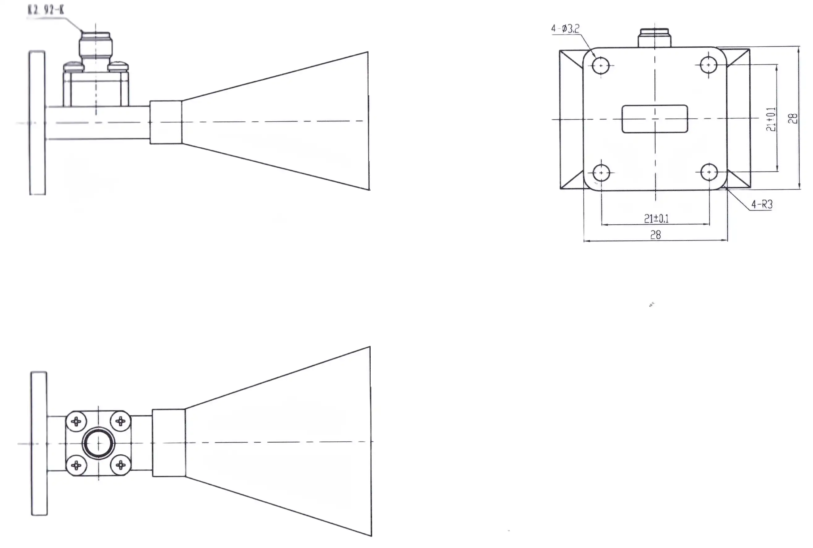
Maximizing Antenna Performance and Application Success
To get the best performance from an antenna, you need to pay attention to its capacity, how it handles polarization, and long-term dependability factors that go beyond the initial requirements for purchase.
Bandwidth Management and Polarization Control
The ratio of opening size to flare length is the main factor that determines operational bandwidth. Designs that are designed for narrow bandwidths (10–15% of the fractional bandwidth) get the highest gain, but the VSWR drops quickly outside the design band. Broadband designs give up 1-2 dB of peak gain to keep matching well across 40-60% of the fractional bandwidth. The right trade-off is determined by the needs of the application.
The clarity of the polarization has a direct effect on the performance of transmission systems and the accuracy of measurements. When you use linear polarization Pyramidal horn antennas, they naturally keep the feeding waveguide's polarization orientation. The polarization can be changed by rotating the horn assembly mechanically, and designs that are dual-polarized have orthomode transducers feeding perpendicular waveguide ports. High-quality designs need to have cross-polarization isolation of more than 30 dB for satellite transmission terminals and antenna measurement uses.
Gain Enhancement and Loss Reduction Strategies
To get the most gain from an antenna, you must first make the aperture as efficient as possible through careful design of its dimensions. To minimize phase error, you need to do math for a balanced flare shape. The quality of the surface finish affects losses, especially above 18 GHz, where the skin depth drops and surface currents are more sensitive to roughness. Surfaces that can support low-loss transmission at millimeter-wave frequencies can be made by electropolishing or precise diamond turning.
When you optimize the feed system, the insertion loss between the signal sources and the antenna opening goes down. Refraction losses are kept to a minimum by using high-quality waveguide parts with precise flange interfaces. It is important to carefully match the resistance when going from one waveguide size to another or from coaxial to waveguide format. In systems where every decibel counts, designers need to pay close attention to every interface that adds more than 0.2 dB of insertion loss.
Durability and Maintenance Considerations
For outdoor projects that are exposed to changing temperatures, water, and UV light, material longevity is very important. Protective coats or anodization are needed on aluminum buildings to stop oxidation, which over time lowers electrical performance. Even tho it conducts electricity a little less efficiently, stainless steel is better at resisting corrosion in marine environments. Sealed radome covers keep the aperture dry in bad weather and reduce signal loss to a minimum when made with the right dielectric materials.
Regular maintenance keeps things running well for a long time. Corrosion, physical damage, or wetness buildup inside the horn structure can be seen with the naked eye. VSWR readings find problems before they have a big effect on how well the system works. Cleaning the flange surface and reapplying the right amount of pressure during system maintenance ensures that the electrical contact stays the same. With these simple upkeep steps, antennas can last longer than 15 years in systems that were built correctly.
Conclusion
Pyramidal horn antenna design uses electromagnetic theory and real-world engineering to make reliable, high-performance parts that are used in mission-critical situations. Knowing how physical measurements, impedance matching, and radiation characteristics are connected helps you make smart choices about what to buy and how to set up your system. Modern simulation tools speed up the optimization of designs, and working with experienced manufacturers makes sure that custom solutions are made to fit the needs of each application. Long-term performance reliability is important for defense, satellite communication, and precision measuring systems. It can be achieved by carefully choosing materials, taking care of the environment, and maintaining systems in the right way.
FAQ
What determines the optimal flare angle in pyramidal horn design?
The best flare angle strikes a balance between the quality of impedance matching and the limitations of physical length. When the angle gets steeper, the antenna gets shorter overall, but the phase error across the opening gets worse, which lowers the gain and makes the beam patterns worse. Angles between 10 and 20 degrees work best for most uses, but the best angle for each job will depend on the frequency range and gain needs.
How does frequency range affect pyramidal horn antenna sizing?
To get the same amount of gain at lower frequencies, the physical measurements need to be bigger. As the frequency goes up, so does the aperture size. For example, a 15 dBi gain horn at 2 GHz is much bigger than the same gain horn at 12 GHz. This wavelength dependence has a direct effect on how the platform is integrated and how the mechanical design is thot out.
Can pyramidal horn antennas handle high-power radar applications?
Because they are simple and don't have any weak parts inside, these antennas work great in high-power situations. Power handling limits are usually caused by air breakdown voltage in the waveguide feed section or at the aperture plane. This voltage can be several hundred kilowatts or more, depending on the frequency and geometry.
Partner with ADM for Custom Pyramidal Horn Antenna Solutions
Advanced Microwave Technologies Co., Ltd has been designing and making Pyramidal horn antennas for more than twenty years. Our ISO 9001-certified factories make precise waveguide parts that can handle frequencies from 500 MHz to 110 GHz. These parts are tested in our 24-meter microwave lab, which has cutting-edge near-field and far-field measurement systems. Our engineering team works with you from the beginning to the end of the development process, whether you need standard gain horns for EMC testing, custom feed assemblies for satellite ground stations, or ruggedized designs for defense radar applications. We can help you stay on schedule with your project by providing fast prototyping, OEM customization, and global shipping support. Our technical experts can help you with all aspects of design and will help you find the best antenna settings for your needs. You can talk to a top provider about your pyramidal horn antenna design needs at craig@admicrowave.com. They are dedicated to providing high-performance, reliable RF solutions backed by strict quality control and expert technical support.
References
1. Balanis, Constantine A. (2016). Antenna Theory: Analysis and Design, 4th Edition. John Wiley & Sons, Hoboken, New Jersey.
2. Milligan, Thomas A. (2005). Modern Antenna Design, 2nd Edition. IEEE Press, Wiley-Interscience, New York.
3. Olver, A.D., Clarricoats, P.J.B., Kishk, A.A., and Shafai, L. (1994). Microwave Horns and Feeds. IEEE Press, New York.
4. Kraus, John D. and Marhefka, Ronald J. (2002). Antennas: For All Applications, 3rd Edition. McGraw-Hill, New York.
5. Stutzman, Warren L. and Thiele, Gary A. (2012). Antenna Theory and Design, 3rd Edition. John Wiley & Sons, Hoboken, New Jersey.
6. Love, A.W. (1976). Electromagnetic Horn Antennas. IEEE Press, New York.
YOU MAY LIKE
 VIEW MORERight Angle Double Ridged WG To Coaxial Adapter
 VIEW MOREEnd Launch Double Ridged WG To Coaxial Adapter
 VIEW MOREHigh Power Waveguide Circulator
 VIEW MOREHigh Power Waveguide Differential Phase Shift Isolator
 VIEW MOREDouble Ridge Waveguide Bend
 VIEW MORECoaxial Broadband Circulator
 VIEW MOREConical Dual circular Polarization Horn Antenna
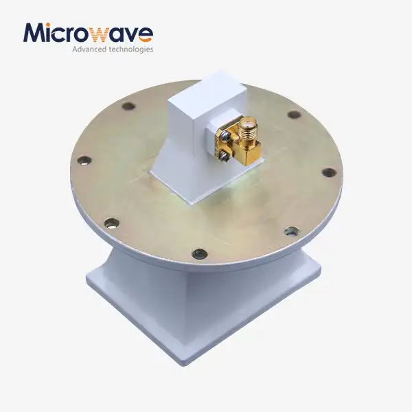 VIEW MOREPyramidal Linear Polarization Horn Antenna
