How to Choose low loss bandpass filters for RF Systems
Selecting the right low loss bandpass filters begins with understanding your system's specific frequency requirements, power handling capacity, and environmental conditions. These filters minimize signal attenuation while allowing only desired frequency bands to pass through, directly impacting system reliability and signal clarity. When choosing, prioritize filters with insertion loss below 1.0 dB for optimal efficiency, evaluate the Q factor for selectivity performance, and confirm compliance with industry standards like RoHS. Whether you're integrating filters into 5G infrastructure, satellite ground stations, or defense radar systems, matching technical specifications to operational demands ensures long-term system performance and avoids costly redesigns.
Understanding Low Loss Bandpass Filters and Their Role in RF Systems
Low-loss bandpass filters are a type of passive RF part that is designed to let signals travel within a certain frequency range while reducing frequencies that aren't needed outside of this range. Unlike high-loss options or ceramic filters, these devices are made to keep the purity of the signal by reducing insertion loss as much as possible. In well-designed systems, this usually means keeping values below 1.0 dB. The basic idea behind how it works is based on resonant structures, like helical resonators or waveguide cavities, which can reach high empty Q-factors of 500 to 5,000, depending on how they are built and what materials are used.
Fundamental Operating Principles
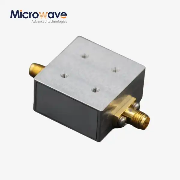
Transverse electromagnetic (TEM) mode transmission in solid coaxial resonators is how coaxial bandpass filters work. To keep skin-effect losses at microwave frequencies to a minimum, the physical construction usually uses high-conductivity materials like aluminum or brass housings that have been plated with silver (3–5 μm thick). The appropriate bandpass response is made by connecting the resonator to magnetic or electric fields. The center frequency stays stable thanks to precise machining tolerances.
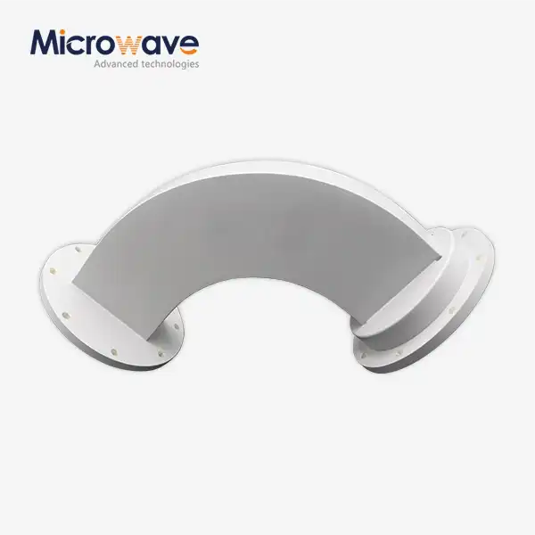
Waveguide bandpass filters work in a different way because they use resonant holes connected by irises or posts inside hollow metal transmission lines. These structures work really well at frequencies above 1 GHz because they have very low insertion loss, are air-filled, and can handle power from kilowatts to megawatts without worrying about dielectric breakdown. Waveguide designs are essential for applications that need strong signal separation with little signal loss because they have a high Q-factor.
Critical Applications Across Industries
In cellular base station infrastructure, these filters separate the transmit and receive bands within duplexers. This keeps sensitive receivers from becoming less sensitive to transmitter noise and keeps outdoor operations reliable even when temperatures change a lot. For high-definition video, data, and voice communications over long-haul links, satellite ground stations need precise filtering to make sure that signals are sent quickly and efficiently. These filters are used in defense radar systems to get rid of unwanted harmonic emissions and protect low-noise amplifiers from high-power jamming signals. They are mechanically strong enough to work on platforms that are in the air or on the water and experience a lot of shaking. As 5G networks and millimeter-wave technologies become more popular, there is a greater need for filters that can handle frequency ranges from 0.5 GHz to 110 GHz. This is to deal with problems like spectrum congestion and interference from adjacent channels.
Key Criteria for Choosing Low Loss Bandpass Filters for Your RF System
To choose the right filtering solutions, you need a way to evaluate them in a way that balances scientific performance with practical limitations. Before deciding what to buy, procurement decisions should start by defining the core system requirements.
Defining System Filtering Requirements
First, figure out what your application's center frequency and capacity requirements are. To keep signals from getting messed up, satellite communication systems that use C-band, X-band, or Ka-band need low loss bandpass filters that are set to specific frequency ranges and have very little passband noise. In emitter uses, the ability to handle a lot of power is very important. The filters must be able to handle continuous RF power without breaking down due to heat or having passive intermodulation (PIM) effects that create false signals.
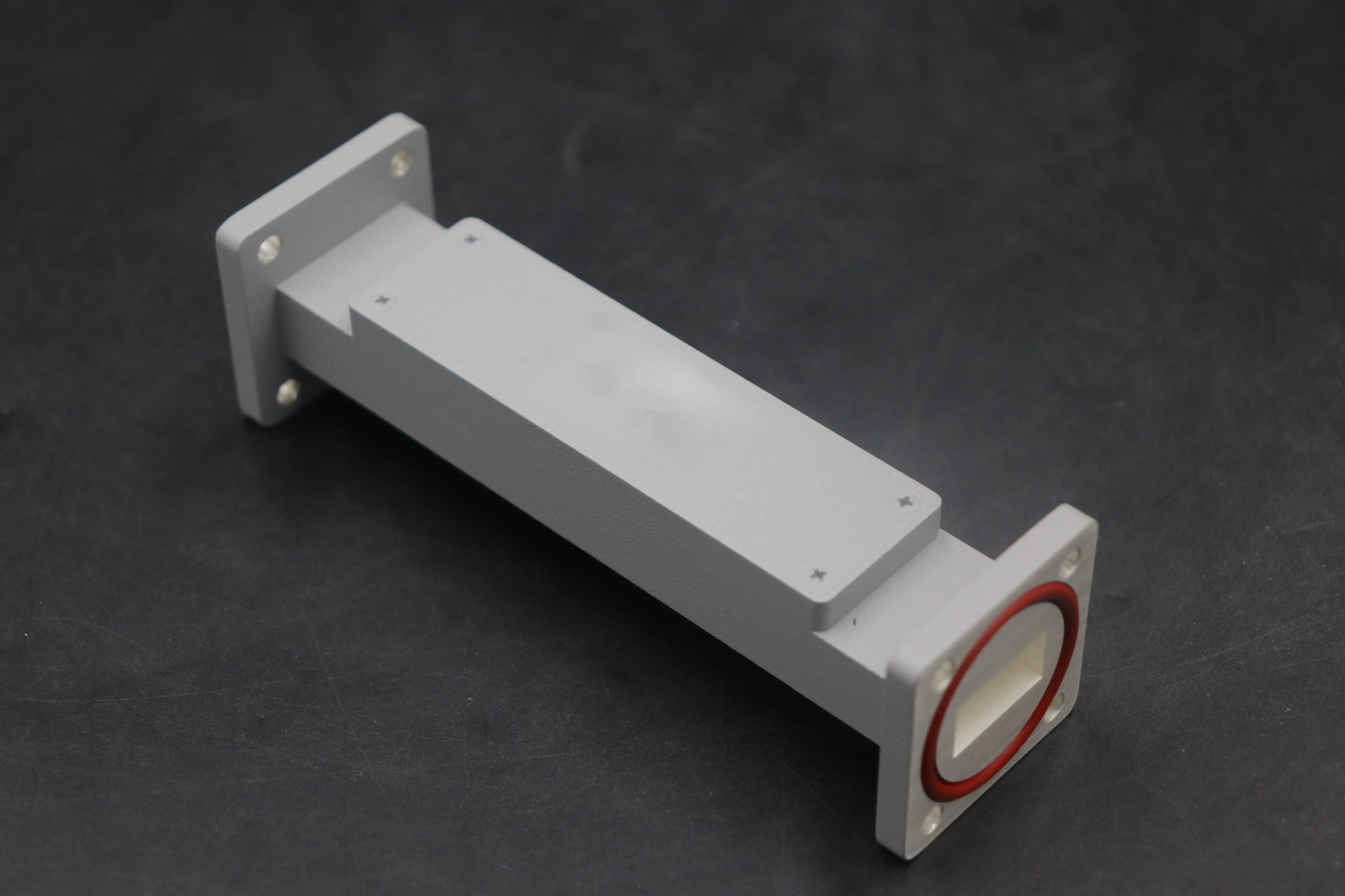

Size, weight, and the ability to handle the environment all have a direct effect on feasibility. For airborne systems, small designs that meet MIL-STD-810 vibration standards are more important than bigger waveguide versions that offer better electrical performance. Stability at room temperature ensures consistent frequency response in all operating conditions. This is especially important for outdoor installations that experience changes with the seasons.
Evaluating Performance Metrics
The Q factor measures how well the resonator works and is directly related to selectivity, which is the filter's ability to tell the difference between wanted signals and interference from neighboring channels. Higher Q values make roll-off traits steeper, which is necessary for current communication systems that use a lot of frequencies. Insertion loss testing shows that the signal stays strong throughout the passband. Values below 0.5 dB are considered excellent for important receiver front-ends where every decibel impacts the system link budget.
Attenuation outside the passband is set by stopband rejection levels. Most antennas need 40–60 dB of suppression to keep out-of-band radiation from overloading them. Group delay characteristics affect signal phase linearity. This is especially important for wideband digital modulation schemes, where too much delay variation causes interference between symbols and lowers the bit error rate.
Balancing Trade-offs in Procurement Decisions
To get the best performance, you have to find the best balance between different parameters. To lower insertion loss, parts often need to be bigger or made of more expensive materials, which raises the cost and makes integration more difficult. Custom filter designs offer exact specs that fit the needs of each system, but they require longer wait times and larger minimum order numbers than catalog goods that are available right away.
More than just electrical specifications need to be thot about when integrating. The types of connectors, mounting ports, and thermal control rules must all match the current RF design. Coaxial filters are flexible for frequencies below 10 GHz, have a much higher Q than ceramic filters, and take up less space than waveguide filters. Waveguide implementations are most common in high-power, high-frequency uses, where their ability to handle more power with less loss justifies their bigger size.
Comparison of Popular Low-Loss Bandpass Filter Types and Leading Solutions in the Market
Knowing the differences between the different filter technologies lets you make smart buying choices that match the needs of your application. Depending on the frequency range, power needs, and connectivity limitations, different building methods offer different benefits.
Technology Comparison Overview
Coaxial resonator filters are in the middle of how simple lumped-element filters are and how well waveguide filters work. They have Q-factors that are much higher than ceramic filters while still being small enough to work below 10 GHz. Because they are built to last and can handle harsh conditions, they are good for cellular systems and public safety networks that are usually set up outside. The silver-plated housings reduce resistive losses so that insertion loss specifications are met over a longer period of time.
Waveguide bandpass filters are the best choice for demanding uses that need to handle a lot of power with little data loss. Working mainly from 1 GHz to more than 100 GHz, these air-filled structures achieve Q-factors that are unmatched because they don't lose any dielectric. Waveguide technology is used to handle kilowatt-level data without worrying about temperature in aerospace radar systems, satellite uplinks, and high-power transmission transmitters. The trade-off is that they are much bigger and cost more to make than coaxial options.
Industry Supplier Landscape
Leading companies cater to specific groups of people by offering a wide range of specialized products. K&L Microwave, which is now part of Dover Corporation, has a large catalog of products that are designed to work best with cellular base stations and spread antenna systems. These products are built to last and can be used outside. Mini-Circuits offers low-cost solutions that can be quickly prototyped, which makes them appealing to research institutions and OEM developers who need to be able to make changes quickly. Murata specializes in small ceramic and coaxial designs for business wireless devices and telecommunications equipment that needs to save room.
Infrastructure-scale filters for macro cell sites are mostly made by European companies like Radio Frequency Systems (RFS). On the other hand, defense contractors make mil-spec waveguide parts that meet strict environmental screening requirements like thermal shock, vibration, and humidity exposure according to MIL-STD-202 protocols.
Custom Versus Standard Solutions
Standard catalog filters are ready to ship right away and have lower unit costs, making them good for uses that can handle a wider range of specifications. Volume pricing is appealing for large-scale deployments where standardization across multiple sites makes operations and stocking up on extra parts easier. Catalog goods, on the other hand, might have slightly worse performance, like more insertion loss or less stopband rejection, so that manufacturers can keep their economies of scale.
Custom filter development meets specific needs that can't be met by standard low loss bandpass filters. The technical investment is worth it for uses that need specific passband shapes, high temperature stability, or unique connector setups. Custom designs usually have longer lead times—8 to 12 weeks—because prototype validation cycles add time to the schedule. Different manufacturers have different minimum order amounts. Some need pledges of 50 to 100 units to spread out the cost of tools, while others will work with smaller batches at a higher cost. When planning purchases, these things should be taken into account during the budgeting and planning stages of the project.
Best Practices for Procurement of Low Loss Bandpass Filters in B2B Environments
Sourcing strategies that work well combine technical needs with business concerns like total cost of ownership, supplier dependability, and quality guarantee. Setting up strong procurement frameworks lowers risks in the supply chain and makes the most of project budgets.
Supplier Evaluation and Sourcing Criteria
The first thing you should do when looking at possible makers is make sure they have the technical skills you need. Check the supplier's datasheets for full S-parameter data across all temperature ranges, making sure that performance margins are higher than the bare minimum. Manufacturers should keep their ISO 9001 certification up to date to show that their quality management system is mature. RoHS and REACH certifications for environmental compliance make sure that global markets follow the rules.
Lead times and the difficulty of planning are affected by where they happen. North American and European suppliers usually have shorter shipping times for customers in the United States, but their prices may be higher than those of Asian makers, who offer lower prices for big orders. Check how experienced the suppliers are in the area where you want to use their products. For example, aerospace companies need suppliers who know about AS9100 aircraft quality standards, and telecommunications buyers want suppliers who have experience deploying cellular infrastructure.
Pricing Models and Negotiation Strategies
Understanding how suppliers set their prices helps you negotiate more effectively. Due to setup costs and engineering overhead, the price per unit is higher for orders that are made in small amounts. When you agree to a certain number of units, you can get lower prices. The savings get bigger at higher volumes, usually between 25 and 50 units, and they get even bigger at 100 units or more. Annual blanket purchase agreements keep prices stable and let you set open release dates that work with project goals.

For unique designs, ask for detailed quotes that break down the costs into ongoing costs (like materials and direct work) and one-time costs (like tools and testing fixtures). Engineering fees that don't happen often may be able to be negotiated or spread out over a number of orders. Different suppliers have different payment terms. For known accounts, standard net-30 terms are usual, but for new relationships, deposits or letters of credit may be needed for special development projects.
Quality Assurance and Risk Mitigation
Tough rules for incoming inspections keep production schedules from being thrown off by failed parts. Testing with a Vector Network Analyzer (VNA) makes sure that all of the S-parameters work as expected. This includes checking for insertion loss, return loss, passband ripple, and stopband rejection. Temperature cycling proves resonance stability, which is especially important for outdoor sites that are exposed to changing weather.
For MIL-STD-810-compliant applications, make sure the supplier has quality documentation such as material certifications, X-ray fluorescence analysis results to check the thickness of the plating, and environmental stress screening results. More tests need to be done on high-power applications to see how corona discharge and multipaction effects work in a vacuum. Setting clear acceptance criteria and inspection processes in buy agreements gives customers a way to return products that don't meet standards and encourages suppliers to do a good job with quality. Instead of depending only on seller licenses, procurement teams have been able to cut field failures by 40% by putting in place thorough inspection processes for arriving goods.
Optimizing Filter Performance and Integration in Your RF System
For rollout to go smoothly, it's not enough to just choose the right components; it also needs to be installed correctly, tuned, and its performance checked regularly. Practical methods for integrating systems make the most of their abilities while reducing the number of times they need to be fixed.
Installation and Tuning Techniques
When it comes to high-power uses, where connector torque limits stop passive intermodulation, mechanical fitting has a direct effect on electrical performance. To get the numbers recommended by the maker, which are usually 8–10 in-lbs for SMA connectors and 25–30 in-lbs for Type-N interfaces, use torque wrenches that have been calibrated. If you tighten the connector too much, the dielectrics deform, and PIM products are released into the receiver bands. If you tighten it too little, the contacts become intermittent, which leads to changes in performance that depend on the power source.
Adjustment screws in tunable filter designs let the center frequency and bandwidth be fine-tuned in the field. Use VNA tools with calibrated reference planes at the filter ports to make the first measurements. Then, compare the measured results to the design specs. Small changes in frequency can usually get a tuning range of ±1% to ±2% without affecting insertion loss. This lets component tolerances be taken into account at the system level. Write down the final setting points so that they can be restored during maintenance.
Real-World Integration Case Study
During the initial rollout, old LTE networks caused problems for a big telecommunications company that was putting in 5G macro cells next to them. Standard catalog filters didn't do a good job of blocking certain frequencies where 5G receivers were overloaded by strong LTE signals. Engineers worked with a specialized filter maker to make custom coaxial bandpass filters that blocked 65 dB of interference at key frequencies while keeping 0.6 dB of insertion loss in the 5G passband.
The solution used advanced coupling methods between resonators and transmission zeros that were placed on purpose at interference frequencies. Before testing in the field at representative cell sites, prototype validation in the lab confirmed performance goals. Full production rollout across 200 cell sites got rid of complaints about interference while keeping the system link budget at its highest level for the widest coverage. The project showed that customized screening solutions can solve real-world problems that catalog goods can't. The investment in custom development was justified by better network performance and fewer customers leaving.
Future Technology Trends
New materials, like high-temperature superconductors, could make a huge difference in the Q-factor, which could cut insertion loss by 50% or more compared to regular metallic resonators. Although they can only be used in cryogenically cooled applications right now, researchers are working on making them work at higher temperatures, closer to those of liquid nitrogen, which would make them more commercially viable for demanding uses.
Using additive manufacturing, you can make resonators with complicated shapes that weren't possible with traditional machining. This improves performance by making the electromagnetic field patterns better. When three-dimensional printing of metal structures is combined with precise electroplating, lead times for custom filters may be cut down, and small batches can be made more cheaply. Spectrum mobility is needed for cognitive radio systems and multi-band infrastructure. Software-defined filtering with digitally tunable components can help with this, but current solutions still have problems when compared to passive options when it comes to insertion loss.
Conclusion
To pick the right low loss bandpass filters, you need to look at their technical performance, the capabilities of the supplier, and the overall costs over their entire life. To have a successful buying process, you must first clearly define your needs, including frequency factors, power handling, environmental conditions, and integration limitations that are unique to your application. Using important measurements like insertion loss, Q-factor, and stopband rejection to check filters makes sure that specifications match system goals. Knowing the pros and cons of coaxial and waveguide technologies helps with architecture choices.
Manufacturers with relevant application experience, quality approvals, and clear paperwork backing inspection methods should be given the most weight when choosing a supplier. Strategic sourcing weighs the benefits of catalog access against the benefits of custom development. Decisions are well-informed by taking into account wait times, volume pricing, and the chance to improve performance. We recommend that procurement teams involve suppliers early on in the system design process so that their engineering knowledge can be used to find the best solutions before architectures are finalized.
FAQ
What advantages do low-loss designs offer compared to standard filters?
Less insertion loss directly protects the system link budget, which can increase the range of communication or make the signal-to-noise ratio better in receiver applications. Every 0.5 dB increase in filter insertion loss leads to the same increase in either emitter power or receiver sensitivity. This means that there are big improvements in performance without any changes to the amount of power used or the need for heat management. Minimal signal attenuation is very helpful for applications that work close to sensitive limits.
Can filters be tuned after installation to accommodate system changes?
A lot of coaxial and waveguide filters have setting screws that let you change the center frequency of the filter within ±1% to 2%. This allows for component tolerances and changes in frequency sharing over the span of the system. To keep performance from dropping during tuning, VNA measurement equipment and trained technicians are needed. Fixed-tuned designs are more stable over time and are better for uses where changing the frequency isn't needed.
How should I decide between standard catalog products and custom designs?
Standard filters work well in situations where the specs that are available meet the performance needs and the delivery plans work with the project's schedule. When unique frequency combinations, harsh weather conditions, or specific performance requirements are greater than what a store can offer, custom development becomes a good idea. Check to see if standard products' poor performance would require system-level redesigns that cost more than the investment in custom filters. Decisions are also affected by the amount of work that needs to be done. For example, large deployments may be worth the cost of custom tools.
Partner with ADM for Precision-Engineered Low Loss Bandpass Filters
Advanced Microwave Technologies Co., Ltd. (ADM) has been making microwave components for over 20 years and supplies them to high-demand B2B markets that need top-notch performance and dependability. We can build both coaxial and waveguide filters that work best for satellite communications, military radar systems, and the rollout of 5G infrastructure. We are a well-known company that makes low loss bandpass filters, and we keep our ISO 9001 and RoHS certifications to make sure that our quality standards meet the needs of buyers around the world.
Every part we make can be thoroughly tested in our 24-meter microwave darkroom, which is equipped with antenna measurement systems that cover frequencies from 0.5 to 110 GHz. We offer OEM solutions that are tailored to your needs, with fast development, full technical support, and low-priced models made for buying in bulk. Email craig@admicrowave.com to talk to our engineering team about your specific filtering needs and get detailed quotes that are made to fit your project. Find out how ADM's proven supply chain skills and technical research and development tools can help you get the most out of your RF system by providing you with precise filtering options.
References
1. Matthaei, G.L., Young, L., and Jones, E.M.T. (1980). Microwave Filters, Impedance-Matching Networks, and Coupling Structures. Artech House.
2. Hong, J.S., and Lancaster, M.J. (2001). Microstrip Filters for RF/Microwave Applications. John Wiley & Sons.
3. Cameron, R.J., Kudsia, C.M., and Mansour, R.R. (2007). Microwave Filters for Communication Systems: Fundamentals, Design, and Applications. Wiley-Interscience.
4. Levy, R., and Cohn, S.B. (1984). "A History of Microwave Filter Research, Design, and Development." IEEE Transactions on Microwave Theory and Techniques, Vol. 32, No. 9, pp. 1055-1067.
5. Hunter, I.C. (2001). Theory and Design of Microwave Filters. Institution of Engineering and Technology.
6. Rhodes, J.D. (1976). Theory of Electrical Filters. John Wiley & Sons.