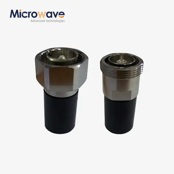
Coaxial Load
Coaxial Load for RF & Microwave Systems — Precision Termination Solutions for Signal Integrity
When a transmission line has no proper termination, reflected RF energy creates standing waves that distort signals and stress active components. A Coaxial Load solves this by absorbing that energy at the line's end and converting it to heat, holding system impedance at 50 Ohms or 75 Ohms. Advanced Microwave Technologies Co., Ltd. (ADM) manufactures these termination components for telecommunications, broadcast, radar, and laboratory environments, supported by an in-house 24m Microwave Darkroom with measurement coverage from 0.5 GHz to 110 GHz.
What Is a Coaxial Load and How Does It Work?
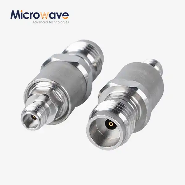
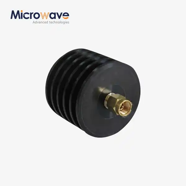
A product — also referred to as a termination, dummy load, or matched load — is a passive, single-port device placed at the end of a transmission line. Its function is to absorb incoming RF energy rather than reflect it back toward the source.
When impedance is not matched at the termination point, the returning energy interferes with the forward signal, producing standing waves. Standing waves reduce power transfer efficiency and can overheat or permanently damage amplifiers and transmitters. Terminating the line at the correct impedance — 50 Ohms in most RF systems, 75 Ohms in cable television and video infrastructure — eliminates this reflection. The absorbed energy dissipates as heat through the load's resistive element and housing structure.


Key Technical Specifications
Parameter | Specification |
Impedance | 50 Ohms / 75 Ohms |
Frequency Range | DC to 110 GHz (model dependent) |
VSWR | ≤ 1.20 (standard commercial grade) |
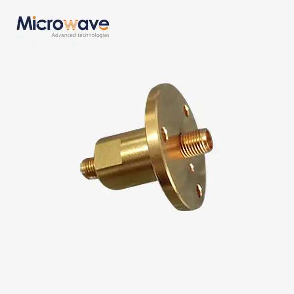
Connector Types | SMA, N-Type, 7/16 DIN, 2.92mm, and others |
Operating Temperature | Up to 125°C (model dependent; refer to derating curve) |
Cooling Options | Air-cooled, fan-cooled, oil-cooled (high-power models) |
Materials | Non-magnetic options available for Low PIM models |
Technical Features
Impedance that stays the same over a wide frequency range. Up to the upper frequency limit that was set, each unit keeps its rated 50 Ohms or 75 Ohms termination from DC. If you run a load past that limit, it will start to behave inductively or capacitively, which will cause high reflections and put attached hardware at risk of damage.
Low performance for VSWR. If the VSWR is less than 1.20, it means that almost all of the energy that comes in is being absorbed instead of reflected. In commercial RF systems, this level is the accepted minimum for protection that you can count on.
Design for high power consumption. The resistive film and building structure are made to handle power that doesn't stop while keeping the surface temperatures safe. There are fan-cooled and oil-cooled versions of these for high-power radar and radio uses.
Configurations with low PIM. Full-duplex systems that use the LTE and 5G bands need better VSWR performance than most systems. The Low PIM Coaxial Load versions from ADM use non-magnetic materials and high-linearity resistive inks with fewer connector junctions. This keeps passive intermodulation products below the levels that would damage sensitive receive lines otherwise.
Application Areas
Infrastructure for telecommunications and DAS. In base station and spread antenna systems, loads close off ports that aren't being used on hybrid combiners and quadrature couplers. This keeps port-to-port isolation and system impedance balance, which stops oscillation and signal loss.
Testing of radar and broadcast transmitters. In order to calibrate and maintain FM, TV, and radar emitters, engineers send all of the power they are sending to a high-power dummy load instead of the antenna. This lets you check the performance without sending out any illegal signals, so operations stay within the rules set by regulators.
R&D and tuning in the RF lab. When calibrating Vector Network Analysers, precision terminations are often used as a common reference part. To get accurate baseline measurements while a part is being made, the load needs to have a known and stable impedance across the whole test frequency range and as the temperature changes.
Spacecraft and satellite parts. To keep interference and signal degradation from happening on long-distance, high-bandwidth transmission paths, satellite communication hardware and aircraft RF assemblies need reliable termination for ports that aren't being used.
ADM's Testing and Engineering Capabilities
ADM has an in-house 24m microwave darkroom that can be used for both near-field and far-field antenna and component readings. The Antenna Plane Near and Far Field Measuring Recombination Chamber at the facility lets you change measurement modes without moving the device being tested.
The testing ranges from 0.5 GHz to 110 GHz, which lets you compare each load to the system's actual operating frequency. ADM has offices in Xi'an, Chengdu, Beijing, Tianjin, and Shijiazhuang, as well as an R&D lab. This lets the team help with custom design requests and give procurement teams direct technical answers.
Selecting the Right Load: Key Parameters
Rating for power. Pick a model that is rated for at least 25–50% more power than your system usually puts out. Along the derating curve, this gap takes into account peak power spikes and the drop in rated capacity that happens as the temperature rises.
The type of connector for a coaxial load. The frequency range and power handling are both directly limited by the connection. When the frequency is above 18 GHz, SMA and 2.92mm connectors can be used. The 7/16 DIN attachment works well for low-PIM, high-power needs at lower frequencies.
Deployment outside. Standard laboratory-grade loads aren't made to be used outside. For outside setups, choose enclosures that keep moisture out and are made of UV-resistant materials to keep them from rusting over time.
Temperature for use. Power ratings that are made public are measured at 25°C. Along the derating curve, the usable power capacity goes down as the ambient temperature rises. It usually reaches zero at 125°C. Installations in closed or thermally limited housings need enough air flow or heat sinking from the outside.
FAQ
Q: How do I pick the right power rating?
A: As a safety measure, you should aim for at least 25–50% more output than usual. This explains why there are high power jumps from the signal crest factor and capacity loss when the temperature outside is high.
Q: To choose a closure, why does VSWR matter?
A: There is a high VSWR when the load sends energy back to the source. The output stage of the amplifier can get too hot from this mirrored power. The standard for business system protection is a VSWR of 1.20 or less.
Q: What's the difference between a normal load and a Low PIM load?
A: Standard loads are designed to work best with VSWR and take in power. To make low PIM versions, nonmagnetic materials and high-linearity resistive inks with fewer junctions are added. This lowers passive intermodulation, which is needed for full-duplex LTE and 5G operation.
Q: Can I use a load that is rated for DC to 3 GHz at 5 GHz?
A: Not really. The load's impedance changes from resistive to inductive or capacitive above its rated upper frequency. This makes VSWR go up, which can hurt hardware that is attached.
Q: Why does the load get hot while it's running?
A: In this case, the load's job is to turn absorbed RF energy into heat. Normal for the surface to be a little warm. If the temperature inside the housing gets close to or goes over the manufacturer's derating limit, either make the ventilation better or choose a model with a higher power rating.
_1733809032116.webp)