





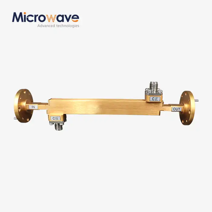
Double-Ridged Waveguide Broadwall Directional Coupler
Double-Ridged Waveguide Broadwall Directional Coupler
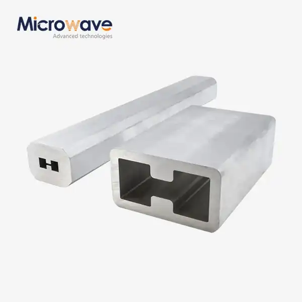
The Double-Ridged Waveguide Broadwall Directional Coupler from Advanced Microwave Technologies (ADM) is a precision passive microwave component designed to sample or combine RF signals across multi-octave bandwidths. In contrast to regular rectangular waveguides, the double-ridged geometry loads the waveguide center capacitively. This lowers the cutoff frequency and increases the single-mode bandwidth that can be used by over 200–300%. This makes it possible for a single unit to work across frequencies from 2 to 18 GHz or 6 to 40 GHz, with VSWR usually below 1.4:1, directivity above 15 dB, and coupling flatness within ±1.0 dB.
What Makes the Double-Ridged Waveguide Broadwall Directional CouplerDesign Different?
Standard rectangle waveguides only work within a small range of frequencies, about 40% of the center frequency. That means engineers have to stack a lot of couplers in a system just to cover a lot of frequencies.
This is directly dealt with by the double-ridged structure. There is a unique electromagnetic field distribution between the two ridge-like protrusions on opposite sides of the broad wall. This shape drops the basic TE10 cutoff frequency while keeping higher-order modes out. This makes the usable band bigger, up to a 3.6:1 frequency ratio in WRD-standard designs.
So, one product can do the work of several separate assemblies, which lowers the weight, insertion loss, and mechanical complexity of the system.
Key Technical Specifications
Parameter | Value / Description |
Waveguide Standards | WRD650, WRD750, WRD180 and others |
Frequency Bandwidth | Up to 3.6:1 ratio (e.g., 2–18 GHz, 6–40 GHz) |
Coupling Flatness | ±1.0 dB across full band |
Directivity | >15 dB (typically >20 dB mid-band) |
VSWR | <1.4:1 |
Coupling Distribution | Tchebyscheff multi-hole coupling array |
Body Material | Aluminum 6061-T6 or Copper alloy |
Surface Finish | Chromate conversion or silver plating |
Flange Types | WRD FP (flat cover) or FDP (grooved gasket) |
Power Handling | Kilowatt-level CW and peak power rated |
Materials and Construction
The Double-Ridged Waveguide Broadwall Directional Coupler body is made by ADM from aluminium 6061-T6 or copper alloys. Both materials have the rigidity needed for environments with air movement and a lot of vibration.
Finishes for the surface can be chromate conversion coating or silver plating, which are applied evenly to lower resistance losses and keep the surface from rusting over time. To lower the chance of multipaction in high-power, non-pressurized applications, alodine-over-silver coatings are suggested.
In order to meet WRD requirements, flange interfaces are machined. You can pick either grooved-gasket FDP flanges or flat-cover FP flanges based on your sealing and VSWR needs.
How the Broadwall Coupling Mechanism Works
Magnetic waves come in through one port and move along the wide wall of the waveguide with two ridges. As the wave moves along, a part of it couples to a secondary port through precisely machined holes in the wide wall. This lets the signal be sampled in a certain direction without stopping the main transmission path.
A Tchebyscheff distribution array is used to order the coupling apertures. This design with many holes keeps the phase balance across the wide band, ensuring that coupling changes stay within ±1.0 dB and directivity stays above 15 dB even at the edges of the band. The waveguide structure can handle more power than coaxial couplers, which makes it perfect for places where high power needs to be sent.
Application Scenarios
Airborne Electronic Warfare (EW) Systems
These couplers are used in systems that jam signals and find threats when they need to cover more than one octave and be small. They let engineers check the output power of an antenna array without having to set up a lot of different hardware chains. The double-ridged shape also lets them work in conditions that are common for airborne platforms.
Tests of High-Power Broadband Radar
The coupler in automated test equipment (ATE) for Synthetic Aperture Radar (SAR) lets engineers sweep full operating bands, characterising TWTs or SSPAs all the time without having to disconnect waveguide connections.
Radiated Immunity Testing with EMC/EMI
These couplers are used in compliance test labs to feed high-power broadband antennas. They do this by giving precise feedback loops to amplifiers that allow for consistent field strength control across octave-wide bands while high-power loads are always on.
Quality Control Process
ADM applies a multi-step QC process to every unit:
· Ridge Gap Tolerance: Verified by CMM (Coordinate Measuring Machine) — micron-level deviations can shift cutoff frequencies, making this the most critical dimensional check.
· VNA S-Parameter Testing: Units are tested with a Vector Network Analyzer to confirm coupling value, flatness, and directivity.
· Flange Planarity Inspection: Flat and grooved flange surfaces are inspected to prevent RF leakage or arcing at high power.
· Insertion Loss Verification: Measured after plating to confirm silver or chromate coatings are uniform and blister-free.
· Pressure Testing: For pressurized airborne applications, sealing tests confirm the unit holds dry air or nitrogen to prevent voltage breakdown at altitude.
Customization and Supply Options
ADM supports custom configurations to fit your system requirements for Double-Ridged Waveguide Broadwall Directional Coupler. Options include:
· Custom frequency range and WRD standard selection
· Coupling value (e.g., 10 dB, 20 dB, 30 dB)
· Flange type: FP flat cover or FDP grooved gasket
· Material and surface finish selection
· Pressurized or unpressurized versions
· Tailored packaging for vibration-sensitive shipments
To discuss a specific configuration, contact ADM's engineering team directly with your frequency range, coupling value, and flange requirements.
FAQ
Q: How does the ridged shape make the bandwidth better than with a regular waveguide coupler?
A: The ridges charge the waveguide, which lowers the TE10 cutoff frequency and keeps the next higher-order mode well above the operating band. This raises the single-mode frequency that can be used from about 40% (standard waveguide) to 200–300% (double-ridged).
Q: How good of a coupling can I expect across the whole band?
A: It is common for a product to have mean coupling accuracy within ±1.0 to ±1.5 dB. Precision CNC machining of the coupling apertures makes it possible to get closer tolerances.
Q: Can these couplers handle a lot of peak power in a vacuum or at high altitudes?
A: In high-power uses that are not under pressure, multiplication risk needs to be managed. For this kind of use, alodine-over-silver coatings and vent holes are suggested. Based on the graphs for different altitudes that come with the unit, peak power ratings should be lowered.
Q: Why does directivity go down as you get closer to the ends of the band?
A: In order for something to be directed, phase cancellation at the coupling holes is needed. At the ends of multi-octave bands, the electrical distance between apertures is not exactly a quarter-wavelength, which makes isolation a little less good. Even at the farthest points, well-designed units keep their directivity above 15 dB.
Q: What kinds of flanges are there?
A: Flanges that meet WRD standards are used. They are either FP (flat cover) or FDP (grooved gasket). It is important to choose the right type to make sure that the VSWR matches and that the system is sealed properly.
Q: What waveguide standards and frequency ranges can be used?
A: WRD650, WRD750, WRD180, and other WRD standards can be used with ADM. If you choose the right standard, the coupler can cover bands like 2–18 GHz or 6–40 GHz all in one piece.
Contact Us
Send your technical requirements or quote requests for Double-Ridged Waveguide Broadwall Directional Coupler to ADM's engineering team at craig@admicrowave.com.
YOU MAY LIKE
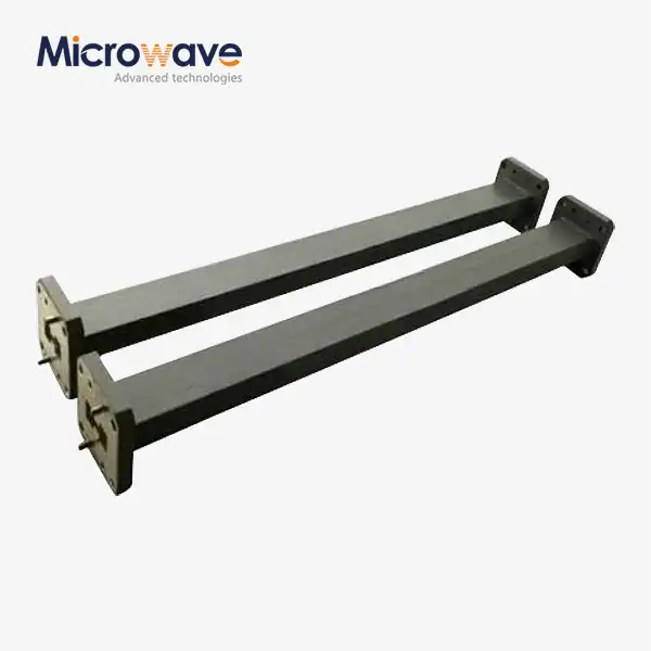 VIEW MOREDouble Ridge Straight Waveguide
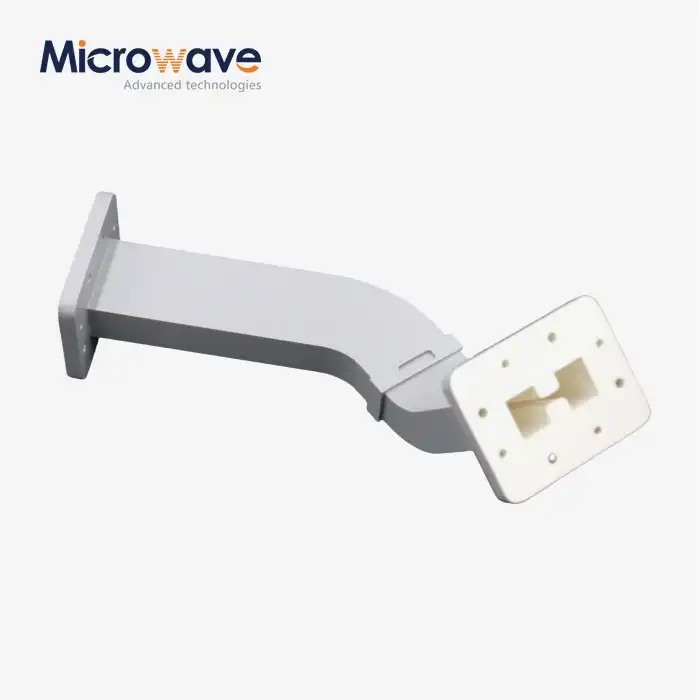 VIEW MOREDouble Ridge Waveguide Bend
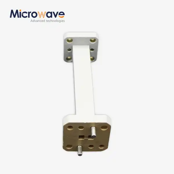 VIEW MOREDouble Ridge Waveguide Transition
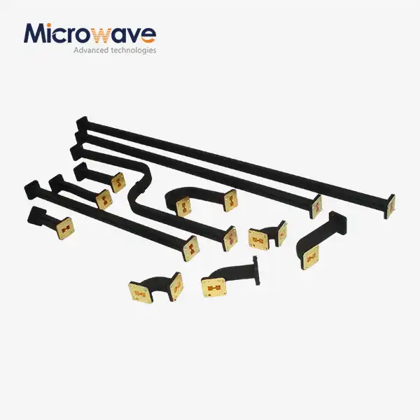 VIEW MOREDouble Ridged Flexible Waveguide
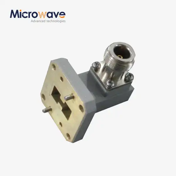 VIEW MOREDouble Ridged WG To Coaxial Adapter
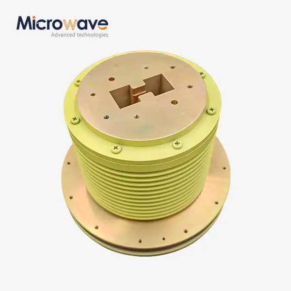 VIEW MOREDouble Ridge Waveguide Rotary Joint
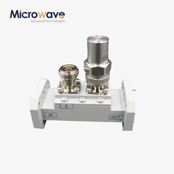 VIEW MOREDouble-Ridged Waveguide Loop Coupler
 VIEW MOREDouble Ridge Waveguide Tube
