How S-Matrix Parameters Define H Plane Tee in Microwave Behavior
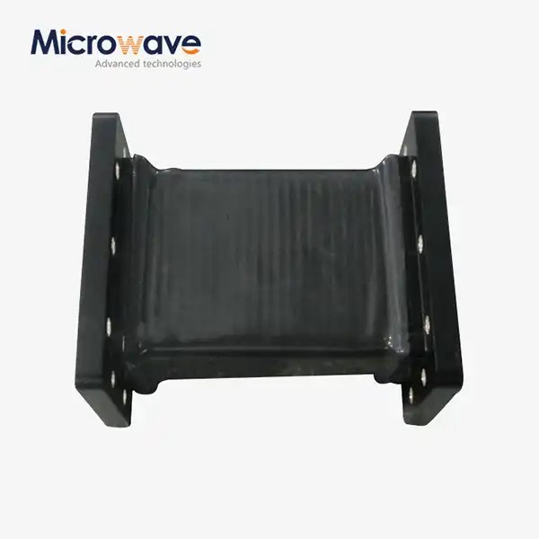
The H plane tee in microwave systems is a three-port waveguide junction where the auxiliary arm connects along the narrow wall of the main waveguide, placing it parallel to the magnetic field (H-field) of the dominant TE10 mode. This physical orientation means signals entering the side arm split equally and in phase between the two collinear ports. Engineers evaluate this behavior using the Scattering Matrix (S-Matrix), a set of parameters that quantify reflection, transmission, and port-to-port signal relationships without disturbing the circuit under test — making S-parameters the standard tool for predicting and verifying junction performance.
Understanding the Fundamentals of H-Plane Tee in Microwave Circuits
Physical Structure and Waveguide Orientation
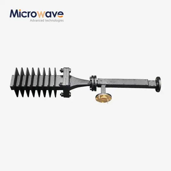
There is a shunt at the H-Plane Tee. Some sources say that its side arm branches off from the main waveguide's wide wall, but ADM's design puts the junction on the narrow wall and keeps the branching arm parallel to the H-field plane. In-phase power division is produced by this setup, which sets it apart from series junctions where phase opposition happens.
How It Differs from E-Plane and Magic Tee Junctions
The extra arm is connected to the broad wall by an E-Plane Tee that runs parallel to the electric field. This makes the phase difference between the output ports 180°. A Magic Tee joins the two ends together and separates the sum and difference ports. The H-Plane Tee, on the other hand, makes in-phase splitting easier and is the best choice when phase coherence across output ports is important for the design.
Role in Microwave Signal Distribution
In phased array antennas, this part is used for company feed networks, in radar emitters for power divider chains, and in satellite ground station front ends for signal routing. Its small size makes it easy to fit inside waveguide systems, and the fact that S13 = S23 in the best case makes network modeling easier in simulation tools like HFSS or CST.
Analyzing H-Plane Tee Performance Through S-Matrix Parameters
Key S-Parameters and What They Measure
Each pair of ports in a three-port junction is shown by an index in the S-Matrix. The input reflection coefficient at port 1 is S11. It shows how much power comes back from a mismatch. With S21 and S31, you can see forward transmission from port 1 to ports 2 and 3. As long as the H-Plane Tee is well-made, |S21| ≈ |S31| ≈ -3 dB and the phase difference between S21 and S31 is close to 0°, which proves balanced in-phase splitting.
A Practical Reading at X-Band Frequencies
There should be a VSWR of less than 1.20 at 9.375 GHz (X-band) for an H plane tee in microwave that is properly matched. This means that the return loss is more than 20.8 dB. The ADM product line has an insertion loss of less than 2.0 dB across all working bands and an amplitude unbalance of less than 0.2 dB. These numbers directly correspond to S-parameter values that procurement engineers can check on a calibrated Vector Network Analyzer (VNA).
Why S-Matrix Methods Are Preferred in Procurement Validation
All ports are terminated in matched loads when S-parameters are recorded. This means that there is no need for short or open standards inside the waveguide. In a single pass, Keysight (PNA series) or Rohde & Schwarz (ZNA series) equipment can record all of the S-matrix data. This non-intrusive method lets quality engineers make sure that every unit meets the requirements listed in the document before putting it into the system. This cuts down on the need for expensive repairs.
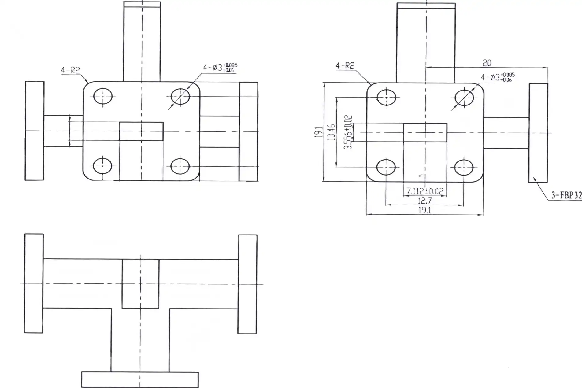
Comparing H-Plane Tee with Other Microwave Components Using S-Parameters
H-Plane Tee vs. E-Plane Tee
The S-matrix phase column shows the most obvious difference. For the E-Plane Tee, S13 and S23 have a 180° phase shift, which means it can be used for balancing mixer inputs or processing differential signals. To feed antenna systems where all parts must radiate in phase, the H-Plane Tee is the best choice because it has a 0° offset. When you choose the wrong junction type, you make beam-pointing mistakes that can't be fixed by any corrections further down the line.
H-Plane Tee vs. Magic Tee and Hybrid Couplers
The Magic Tee is basically an E-Plane Tee and an H-Plane Tee joined together into a single four-port structure. It gives port separation that neither of the separate tees does. Hybrid couplers (90° and 180° types) split signals in the same way, but they introduce a fixed 90° or 180° phase shift by design. The H-Plane Tee has a better S-parameter profile than these more complicated options when the application needs simple, low-loss, in-phase power division with few ports.
Choosing the Right Component for Your Application
The choice is based on two S-parameters: the phase relationship between the output ports and the amount of return loss that is allowed at the input. Here is a quick list of common situations:
- Phased array feed networks: pick the H-Plane Tee. The S13 and S23 phases must match within ±2°.
- Balanced mixer inputs: pick the E-Plane Tee, which needs a 180° phase difference.
- Diplexer or combiner with port isolation: pick the Magic Tee or a hybrid coupler.
- Wideband power splitting: check the insertion loss S21 across the whole band before committing.
These differences help buying teams write accurate part specs and avoid making mistakes when the supply chain is interrupted.
How to Choose and Procure the Best H Plane Tee for Your Microwave Applications
Selection Criteria Grounded in S-Parameter Data
Start with the frequency band you want to use and match it up with the waveguide standard (WR-90 for X-band, WR-62 for Ku-band, etc.). Then set the VSWR budget. Most system-level link budgets allow a maximum VSWR of 1.25:1 at each point. ADM's H plane tee in microwave line has frequency ranges from 0.332 GHz to 6.0 GHz in lower bands. It has flange options like FDP and FBP types to match waveguide infrastructure that is already in place.
Material and Finish Decisions
Choice of material has a direct effect on ohmic loss and longevity in harsh environments. The main choices in ADM's collection are listed below:
- Aluminum (6061): A chromate conversion finish that is light, cheap, and good for use in the air and on the ground where weight is an issue.
- Oxygen-free copper: Superior conductivity for high-power CW uses, and the silver-plated finish lowers the resistance at the surface.
- Gold-plated variants (FUGP): Best at resisting rust in wet or salty places; used most often in long-lasting defense systems.
Because surface conductivity changes skin-depth losses, especially above 10 GHz, each finish choice has a unique S-parameter baseline. If you choose the right finish during the design stage, it won't affect the performance in the field.
OEM and Bulk Procurement Considerations
ADM provides OEM services such as quick development, custom frequency setting, and low prices for large orders with long-term agreements. When buying in bulk, purchasing managers should ask for full S-parameter data files (in Touchstone.s3p format) and measurement reports checked by coordinate measuring machines (CMM) to MIL-DTL-85 flange standards as part of the acceptance package.
Practical Tips for Integrating H-Plane Tee in Your Microwave Circuit Design
Pre-Integration S-Parameter Verification
Measure S11 at the input port of any H-Plane Tee before putting it in a subsystem. Make sure that the two output ports are terminated in precisely matched loads. If the return loss is less than 20 dB across the whole operating band, it means that the internal matching post or inductive iris is working properly. Any unit with a return loss greater than -15 dB should be thrown out; junction reactance adjustment is not good enough and will lower the system noise number.
Common Design Pitfalls to Avoid
The most common point of failure is the quality of the flange contact. Even a gap of 0.025 mm between connecting lips lets RF flow, which raises S11 and adds unwanted radiation. Before tightening nuts to the given value, you should always use an optical flat or CMM to make sure the head is flat. It's important to use the right torque sequence. To keep thin aluminum flanges from warping, use a cross-pattern.
Testing and Long-Term Maintenance
Run a full four-port S-parameter sweep with a calibrated VNA after integration. Look at the standard datasheet numbers and compare the amplitude and phase of S21 and S31 to them. Every year, check the S-parameters of systems that are outside or in pressurized enclosures. If measures taken after installation don't match the specs, ADM's technical support team can help with fixing by giving engineering-level analysis instead of standard customer service answers.
Conclusion
There is no better way for engineers and buying workers to figure out how a waveguide junction will work in a real system than to use the S-Matrix. The S11 return loss, balanced S21/S31 transmission, and phase coherence between output ports are the most important parameters for the H-Plane Tee. They translate the choices made during the physical design into predictable, measurable system performance. ADM makes many different H plane tee in microwave parts that are made to ISO 9001:2008 and RoHS standards. These parts can be made from different materials and can be customized by the original equipment manufacturer (OEM) to meet the specific needs of aircraft, defense, and satellite communication. Giving clear S-parameter criteria from the start gets rid of guesswork and shortens the time it takes to buy something.
FAQ
What does the S-Matrix actually tell you about an H-Plane Tee?
There is a full picture of how each port works with the others in the S-Matrix. It's S11 (how much data comes back at the input), S21 and S31 (how much power gets to each output port), and the phase difference between S21 and S31 that matter the most for an H-Plane Tee. In a perfect device, both outputs have the same amplitude and a phase difference of 0°, which proves that the power is being split in phase.
How does the H-Plane Tee differ from an E-Plane Tee in practice?
The E-Plane Tee splits power 180° out of phase, while the H-Plane Tee splits power in phase. This is not a small change; if you put the wrong junction type into an antenna array, the beam will go in the wrong direction. Before choosing a component, you should always check the S-parameter phase column in the datasheet.
Where can I source custom or standard H-Plane Tee components?
ADM (admicrowave.com) makes both regular catalog units and fully unique designs for different frequency ranges, power levels, and flange arrangements. Rapid development and full S-parameter acceptance tests are part of custom orders. For questions, email craig@admicrowave.com immediately.
Can an H-Plane Tee handle high-power applications?
Yes. How much power it can handle relies on its internal shape and material. Units made of aluminum can handle normal amounts of telecommunications power, while units made of copper or silver can handle higher CW power. The peak power threshold goes up even more when the waveguide assembly is under pressure because the dielectric breakdown voltage goes up.
Partner with ADM for Your H-Plane Tee in Microwave Supplier Needs
Every part that ADM makes is based on more than 20 years of experience making things. Our H-Plane Tee line works with frequencies from less than 1 GHz up to H plane tee in microwave frequencies. It has VSWR ≤ 1.20 and insertion loss ≤ 2.0 dB specs, backed up by full S-parameter test data. Certification to ISO 9001:2008 and compliance with RoHS are standard. You can email our engineering team at craig@admicrowave.com to get price quotes and datasheets, whether you need normal stock units or a fully engineered OEM option.
References
1. Pozar, David M. Microwave Engineering, 4th ed. Wiley, 2011.
2. Collin, Robert E. Foundations for Microwave Engineering, 2nd ed. IEEE Press / Wiley-Interscience, 2001.
3. Montgomery, C. G., Dicke, R. H., and Purcell, E. M. Principles of Microwave Circuits. MIT Radiation Laboratory Series, McGraw-Hill, 1948.
4. Matthaei, G., Young, L., and Jones, E. M. T. Microwave Filters, Impedance-Matching Networks, and Coupling Structures. Artech House, 1980.
5. Bahl, Inder J. Microwave and RF Engineering. Wiley, 2003.
6. Rizzi, Peter A. Microwave Engineering: Passive Circuits. Prentice Hall, 1988.