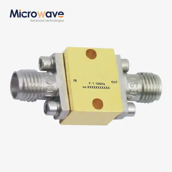
Active Limiter
Active Limiter for RF & Microwave Receiver Protection | Advanced Microwave Technologies
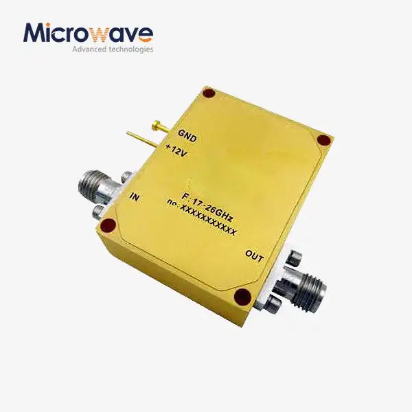
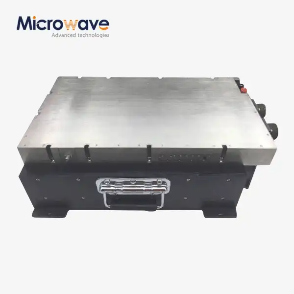
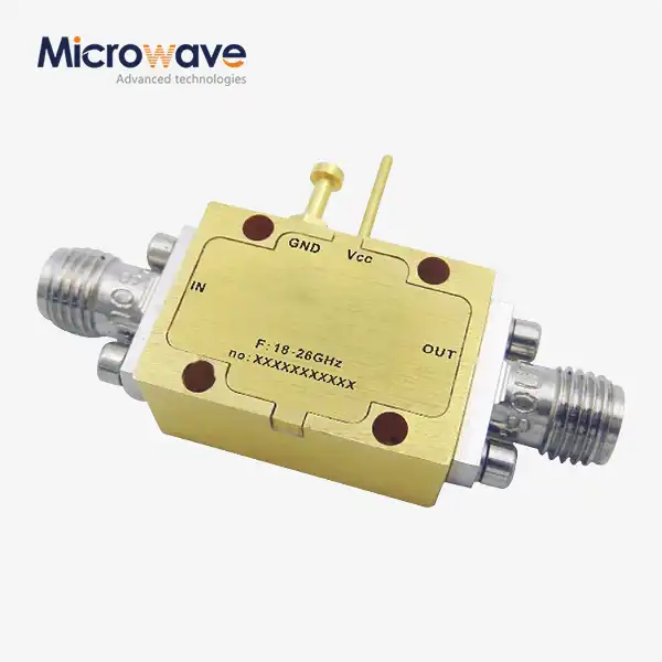
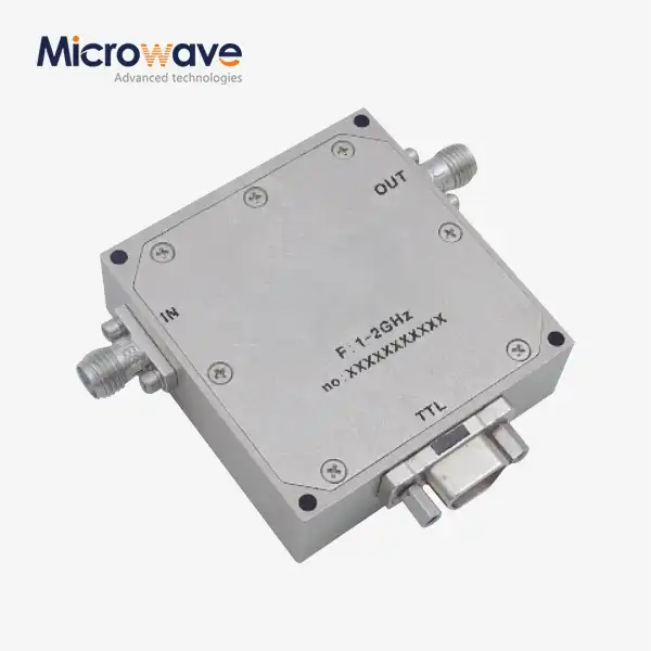
Advanced Microwave Technologies (ADM) designs and manufactures Active Limiter components for RF and microwave receiver protection in radar, electronic warfare, satellite communication, and 5G infrastructure applications. Built on GaN or GaAs MMIC technology, each unit delivers insertion loss as low as 0.5 dB in X-band, flat leakage of +10 to +15 dBm, and recovery times under 100 nanoseconds. ADM's engineering team brings more than 20 years of microwave product development experience across a frequency range of 0.5 GHz to 110 GHz.
What Is an Active Limiter and How Does It Work?
The product is an RF and microwave control component designed to protect sensitive receiver circuits — particularly Low Noise Amplifiers (LNAs) — from high-power input signals that could cause damage or operational failure.
Unlike passive limiters that rely on diode rectification alone, this type of device uses a multistage detection architecture. A Schottky diode detector continuously monitors the incoming RF power level. When the signal exceeds a predefined threshold — typically between -10 dBm and +10 dBm — the detection circuit triggers a bias current to a PIN diode or FET, driving it into a low-impedance state that shunts excess energy to ground.
This architecture separates small-signal performance from large-signal protection. The receiver path maintains low insertion loss during normal operation, and the limiting function activates only when the input power crosses the programmed threshold.

Key Electrical Parameters
The table below lists typical performance values. Contact ADM to confirm specifications for your target frequency band and operating conditions.
Parameter | Typical Performance |
Insertion Loss | < 1.0 dB (as low as 0.5 dB in X-band) |
Flat Leakage | +10 to +15 dBm under high input drive |
Limiting Threshold | -10 dBm to +10 dBm (adjustable via bias) |
Recovery Time | < 100 ns (Schottky-FET topology) |
Spike Leakage | Nanosecond-scale response |
Operating Temperature | -55°C to +85°C |
DC Bias Required | Vcc + optional negative gate bias (Vgg) |
All values are typical at room temperature unless otherwise noted. CW power handling differs from peak pulse power — request a datasheet for the full rating breakdown relevant to your application.
Input VSWR


Output VSWR Output power/Input power

 Materials and Construction
Gallium Nitride (GaN) or Gallium Arsenide (GaAs) MMIC technologies are used to make ADM's limiters. GaN and GaAs can handle more power while taking up less space than older silicon PIN versions.
Each unit is housed in a QFN or ceramic package that can't be opened. Environmental screening follows the steps in MIL-STD-883, which cover protection to thermal shock and moisture. There is an active bias network and temperature compensation circuitry built in to help keep the threshold constant over the military temperature range of -55°C to +85°C.
Application Scenarios
Electronic Warfare and SIGINT Receivers
Military Signal Intelligence systems need antennas that can pick up weak signals even when they are close to sources of high-power jamming. Putting the Active Limiter right after the antenna stops the LNA from burning out and keeps the receiver's sensitivity high enough to pick up low-level signals.
T/R Modules for Phased Array Radar
A lot of Transmit/Receive units are used in modern AESA radars. It keeps the receive channel safe during the high-power transmit pulse and from reflections from close targets. The radar's minimum detection range is directly related to how long it takes to recover.
5G Massive MIMO Infrastructure
In cities with lots of people, unsynchronised transmitters and radar band interference from nearby cells can make small cell receivers too busy. Limiter circuits keep the receive line safe and keep the link working well even in places with a lot of radio waves.
Quality Control Process
Before a unit is shipped, ADM goes through a multi-step inspection process.
High-Power Burn-In Testing
At +85°C, RF power survival tests are done on each unit at 1–3 dB above the rated P1dB point to look for early breakdowns and thermal stress in the active diode junctions.
Checking of S-Parameters
Testing with a Vector Network Analyser (VNA) confirms that there is return loss, VSWR, and insertion loss over the whole operating bandwidth. Deviations from the specs are used to find problems with the bond wires or semiconductors.
Power Profiling for Leakage
It can measure both flat and spike leakage patterns with a pulse power meter. QC engineers make sure that the turn-on threshold is within the tolerance window that was set. If there is a problem with the active bias circuit, the threshold can drift, which can put parts further down the line outside of their safe operating range.
Environmental Stress Screening
As required by MIL-STD-883 and JEDEC, all hermetic packages go through fine and gross leak tests as well as temperature cycling from -55°C to +125°C. This proves that the die attachment is solid and the wire bond is reliable when the temperature changes.
Why Choose ADM?
ADM has a 24-meter microwave darkroom with an antenna plane near and far field measuring recombination chamber that can be used for both near-field and far-field measurements from 0.5 GHz to 110 GHz. This feature is directly used to check how well the Active Limiter works at the frequency bands that customers choose.
The engineering team has more than 20 years of experience developing waveguide components, coaxial components, cable assemblies, and microwave antennas. This gives project teams knowledge at the component level as well as an understanding of how to integrate systems more generally.
For non-standard frequency bands, package forms, and bias needs, you can get configurations that are made just for you. Get in touch with the ADM engineering team directly to talk about specs or ask for a datasheet.
FAQ
Q: What is the primary advantage of a product over a passive limiter?
A: The main difference is being able to separate performance for small signals from protection for large signals. They can get lower insertion loss and a lower limiting cutoff at the same time because they use external DC bias to control diode impedance. The level of a passive limiter is set by the diode's built-in junction potential. This makes a fixed trade-off that usually hurts the receiver's sensitivity.
Q: Does the device need a power supply from somewhere else?
A: Yes. To work, it needs a DC voltage source (Vcc) and sometimes a negative gate bias (Vgg). In the event that DC power is lost, the device switches to a passive limiting mode, which is less effective than active operation.
Q: How does the temperature change how well something works?
A: The characteristics of a diode junction change as the temperature changes, which can lead to threshold drift. In ADM's units, this effect is lessened by temperature compensation circuitry that works from -55°C to +85°C. If the application needs a tighter threshold tolerance, check the compensation specification with ADM engineers first.
Q: Can the device take both CW power and pulsed power?
A: As you can see, these gadgets are mostly designed for pulsed power uses, like radar. When CW input is kept up for a long time, heat builds up and can reach junction temperature limits. Most of the time, CW power ratings are smaller than peak pulse power ratings. Ask for the datasheet to find out the exact CW and pulse levels that will work for your situation.
Q: What does Recovery Time mean, and why does it matter?
A: Recovery Time is how long the gadget keeps weakening the signal after a high-power pulse is over. In radar systems, extended recovery makes a range blind zone right after each pulse is sent, which makes it impossible to see objects that are close. The parameter table shows that ADM's Schottky-driven FET topology can achieve recovery times of less than 100 ns.
Q: What kinds of package formats are there?
A: ADM has hermetically sealed QFN and ceramic packages. Based on the needs of system integration, we can talk about custom package formats and connector interfaces.
Contact Us
Contact ADM's engineering team at craig@admicrowave.com to discuss specifications, request a datasheet, or get a custom quote for your Active Limiter application.