





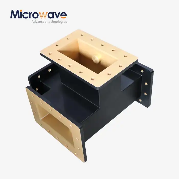
H-Plane Tee
H-Plane Tee Waveguide Junction for Precision Power Splitting in Microwave Systems
Advanced Microwave Technologies (ADM) makes H-Plane Tee parts, which are also called Shunt Tee or H-Plane Waveguide Junction. These parts can be tested from 0.5 GHz to 110 GHz. The extra arm is attached to the main waveguide's narrow wall and is lined up with the primary TE10 mode's magnetic field vector. This shape splits power evenly between the two arms that are collinear, which makes it a solid building block for microwave systems used in space, radar, and industry.
What Is an H-Plane Tee?
A product is a waveguide part with three ports that can be used to split or combine microwave power. When you connect Port 3 (the side arm) to the main collinear guide made up of Ports 1 and 2, it goes in a straight line.
It works like a parallel connection in terms of circuits. A signal entering the side arm splits equally in magnitude and phase between the two output ports — a relationship expressed by the Scattering Matrix condition S13 = S23. The product is different from its E-Plane counterpart because it has an in-phase output. This makes it good for beamforming networks and high-power transmission lines where signal synchronisation is important.
Key Technical Properties
If you don't fix the inductive reactance that happens at the physical joint inside a product, VSWR will go down. ADM's units have internal matching parts like posts, screws, or inductive irises that are tuned to get rid of that reactance and keep the VSWR below 1.25:1 over the given operational bandwidth.
There is ±2 degrees of phase balance between the two output ports that are lined up with each other. This is proven by measuring the S13 and S23 phase angles across the whole frequency range with a calibrated multi-port VNA.
Materials and Construction
ADM makes parts for products out of Aluminium (6061) or Oxygen-Free Copper and copper alloys, which are chosen based on the application's structural and thermal needs.
Silver or gold plating is put on the inside and outside at a thickness of 3–5 µm. This lowers the chance of passive intermodulation (PIM) that happens when plating material inside the waveguide comes loose. It also lowers the ohmic losses at the conductor surface.
Machined flanges meet MIL-DTL-85 and IEEE interface flatness standards, which makes sure that they fit together correctly and don't leak during system integration.

Electrical & Mechanical Specifications
Parameter | Specification |
Configuration | Three-port (Ports 1 & 2: collinear; Port 3: side arm) |
Operating Mode | Dominant TE10 mode |
VSWR | < 1.25:1 across operational bandwidth |
Phase Balance | ≤ ±2° between collinear output ports |
S-Parameter Condition | S13 = S23 (in-phase equal split) |
Material | Aluminum 6061 / Oxygen-Free Copper |
Surface Finish | Silver or Gold plating, 3–5 µm |
Power Handling | High CW and pulsed power capability |
Operating Temperature | –55°C to +85°C |
Flange Standard | MIL-DTL-85 / IEEE waveguide flange specifications |
Matching Element | Internal post, screw, or inductive iris |
Application Scenarios
Phased Array Antenna Feed Networks (Defence and Aerospace)
The H-Plane Tee is an important part of corporate feed networks because it splits transmitter power among several radiating elements while keeping the in-phase relationship needed for precise beam shaping. The temperatures of the parts are rated to work in a range from –55°C to +85°C.
Industrial Microwaves with a Lot of Power
Tee joints send power from several magnetrons to several applicators in industrial processing systems. They can handle continuous-wave (CW) power without dielectric breakdown, which means they can be used to make plasma and dry materials.
Radar Signal Processing via Monopulse Comparators
Together with E-Plane Tees, these items work in radar receiving chains to make hybrid comparator networks that add signals from antenna quadrants to figure out range and elevation. Units can be ordered with surface finishes that work well in salt-fog situations for naval radar environments.
Quality Control Process
Before sending out any waveguide tee parts, ADM puts them through a multi-stage quality process.
Testing the VNA's S-Parameters: Full-band sweep testing checks the VSWR (return loss), insertion loss, and isolation. The ±2° specification is used to measure the phase balance between the output ports.
CMM Dimensional Inspection: Coordinate Measuring Machines verify internal waveguide dimensions and flange flatness to MIL-STD specifications. RF leakage and arcing can happen in field setups when the flange contact is not good enough.
XRF Plating Verification: X-ray fluorescence testing proves the thickness of the silver or gold plating at 3–5 µm. Adhesion testing is also done to lower the risk of internal flaking and PIM formation.
Pressure and Leak Testing: For systems that are under pressure, pneumatic testing makes sure that the seals are hermetic and keeps water out, which over time hurts the electrical performance.
Customization and Supply Options
ADM lets you make your own H-Plane Tee shapes for a number of different waveguide bands. You can choose the type of flange, the plating, the matching configurations, and the target frequency ranges that work best for your system.
The engineering team works directly with customers to set tolerances for dimensions, needs for power handling, and environmental standards. ADM has an R&D lab with branches in Xi'an, Chengdu, Beijing, Tianjin, and Shijiazhuang. These labs provide engineering help for global projects that need it in the regions.
Send your needs to craig@admicrowave.com to talk about a particular configuration.
FAQ
Q: What is the main difference between a product and an E-Plane Tee in terms of electricity?
A: It's a shunt tee, which means that the outputs are all the same in terms of magnitude and phase. The E-Plane Tee is a series tee, which means that the outputs are the same size but 180 degrees out of phase. Because these traits support each other, they can play different roles in hybrid comparator networks.
Q: Why does VSWR usually look bad on a product that hasn't been mated?
A: The physical joint makes a sharp break that works like inductive reactance. Professional units have a matching element, like a screw, post, or iris, that is tuned to get rid of this reactance and bring back a good VSWR across the operating band.
Q: Can this item be used as a power combiner?
A: Yes. Because of reciprocity, signals can come in through the arms that are next to each other and join at the side arm. The messages coming in must be in phase and have the same amplitude. When power comes in out of phase, it can reflect or couple inefficiently, which can damage the source.
Q: What determines the amount of power it can handle?
A: The breakdown voltage of the medium inside the waveguide limits the peak power. The average power is limited by how well the metal and flanges conduct heat. Putting pressure on the waveguide system can make it able to handle more power.
Q: How is phase balance checked while testing?
A: The phase angle of S23 is subtracted from S13 across the given frequency band using a multi-port VNA that has been measured. ADM checks each unit's phase imbalance against the ±2° standard.
Q: What types of waveguide bands and flanges does ADM support?
A: ADM makes products in standard waveguide bands and can also work with custom frequency ranges. The types of flanges and plating materials are chosen based on the needs of your system interaction. For a direct answer, send your configuration information to craig@admicrowave.com.
Contact Us
Send your H-Plane Tee specifications or inquiries to craig@admicrowave.com. The ADM engineering team will review your requirements and respond with relevant technical and commercial information.
YOU MAY LIKE
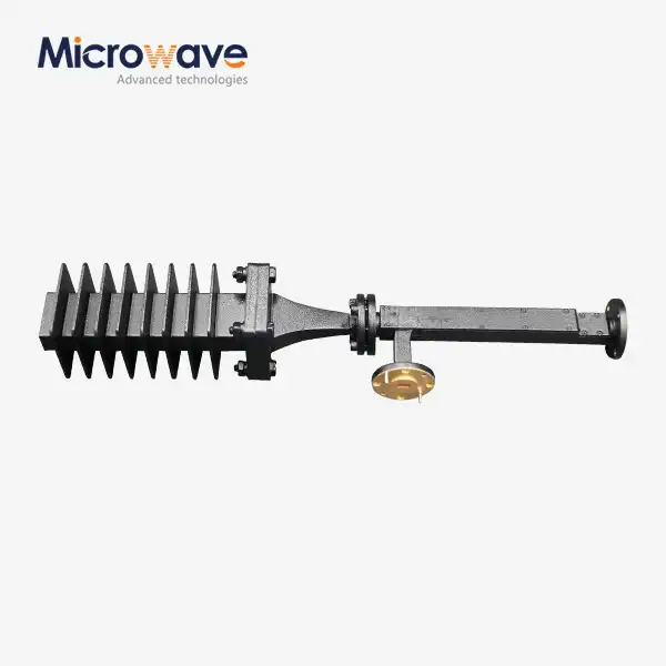 VIEW MOREWaveguide Fixed Attenuator
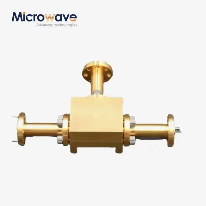 VIEW MOREWaveguide Power Divider
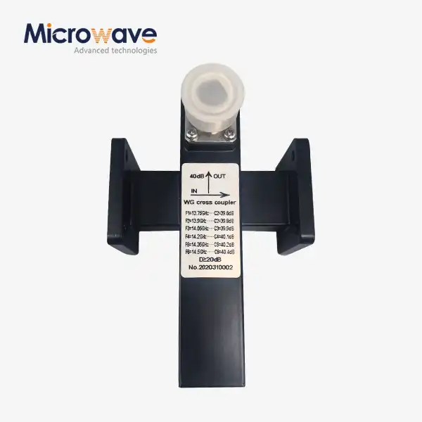 VIEW MORECrossguide Directional Coupler
 VIEW MOREHigh Power Waveguide Differential Phase Shift Circulator
 VIEW MOREWG Isolator
 VIEW MOREWG Bandpass Filter
 VIEW MOREWaveguide Single Channel Rotary Joint
 VIEW MOREWG Dual-Channel Rotary Joint
