





How Does Subreflector Blockage Affect Cassegrain Antenna Efficiency?
Subreflector blockage is one of the most consequential yet frequently underestimated factors shaping the performance of a cassegrain antenna. In dual-reflector antenna systems, the secondary hyperbolic subreflector intercepts and redirects energy from the primary parabolic dish back toward the feed horn mounted at the vertex. When this subreflector physically occludes part of the main aperture, it disrupts the radiated wavefront, degrades aperture efficiency, raises sidelobe levels, and measurably reduces system gain. For procurement engineers and satellite system integrators, understanding this phenomenon is essential to making sound sourcing decisions.
Understanding Subreflector Blockage in Cassegrain Antennas
The Geometry Behind the Problem
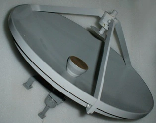
Along the main dish's centerline, the subreflector is held in place by support struts inside the antenna's aperture plane. Due to its actual presence, a circle of shade is cast across the lit aperture. When electromagnetic energy hits this blocked area, it doesn't add to the main beam; instead, it spreads, bends, and feeds into sidelobe structures. The blockage ratio is the ratio of the subreflector's projected area to the total aperture area. Values as small as 0.1 have real effects. Industry research consistently shows that a blockage ratio of just 5% can lower aperture efficiency by 3% to 6% while also increasing near-in sidelobes by several decibels. This is a major issue for ITU-R S.580 sidelobe mask compliance.
Electromagnetic Consequences on Radiation Pattern
In addition to the loss of raw gain, diffraction around the edge of the subreflector causes phase errors across the aperture. These phase mistakes make the main beam wider and mess up the Cassegrain antenna's ability to separate cross-polarization. Cross-Polarization Discrimination (XPD) values above 30 dB are needed by satellite earth stations. Even a small blockage-induced phase distortion can cause performance to go beyond what is expected. The problem is made worse by the fact that the structural supports block struts, which causes more scattering that shows up as higher sidelobe floors. This has a direct effect on the co-channel interference margins in dense satellite orbital arc environments.
Causes and Effects of Subreflector Blockage on Antenna Efficiency
There are two main types of root causes of blockage: geometric limitations that can't be changed and mistakes that can be avoided during installation.
Because the subreflector has to be big enough to catch and redirect the whole cone of energy from the primary, it has to follow certain geometric rules. Cassegrain antennas with shallow f/D ratios (0.6–0.8, common for Cassegrain designs) need a fairly large subreflector, and no amount of fine-tuning in the manufacturing process can get rid of the shadow it casts. On top of the subreflector disk itself, the mounting gear for the feed horn and the support legs for the subreflector add more blockage.
Installation and alignment mistakes are in the "avoidable" group. If a subreflector is moved axially, even by a tiny fraction of a millimeter at Ka-band frequencies, it moves the phase center away from the best convergence point. This causes beam squint and gain loss that can be worse than the loss caused by the blockage itself. Near-field antenna range testing at ADM's 24-meter microwave lab has shown that phase center shift often causes systems that aren't properly set up to lose 0.2 to 0.5 dB of gain.
All of these factors put a direct strain on the system link budget. For example, if the receive gain goes down by 1 dB, the send power or modulation strength needs to go up by the same amount to keep the same data throughput. This makes the whole signal chain more expensive and complicated.
Optimization Strategies to Minimize Subreflector Blockage
Attention needs to be paid during the planning phase, the manufacturing phase, and the commissioning phase to lower the effect of blockages. In professional antenna engineering, these are the main ways that problems are dealt with:
- Offset-fed dual-reflector configurations physically remove the subreflector from the projected aperture of the main dish, eliminating central blockage entirely. Offset Cassegrain and offset Gregorian geometries achieve this at the cost of greater structural complexity and asymmetric beam characteristics that must be compensated for in the feed network design.
- Subreflector sizing optimization through computational electromagnetics (CEM) uses full-wave simulation tools such as GRASP or FEKO to find the smallest subreflector diameter that still blocks all the important energy from the primary. This reduces the size of the blockage shadow without lowering the lighting efficiency.
- Vertex matching plates and shaped sub-reflector profiles to spread out center retroreflections stop standing waves from building up between the feed and subreflector surface. This keeps the VSWR fixed (usually below 1.3:1) across the working band.
- Precision laser tracker and photogrammetry alignment during installation verifies that the subreflector phase center aligns with the primary's focal point within tolerances matched to the operating wavelength — a critical acceptance step for Ka-band and higher-frequency systems.
All of these strategies work together to keep aperture efficiency high and keep the link budget from losing money in ways that can only be seen during full-system integration testing.
Comparing Cassegrain Antenna Performance: With vs. Without Subreflector Blockage
Comparing the performance of blocked and unblocked configurations using numbers shows important differences. If you have a 10% linear blockage ratio (about 1% area blockage in a small-diameter dish) in a symmetric cassegrain antenna, the sidelobe will rise by about 1-2 dB, and the gain will drop by up to 0.5 dB. As the width of the aperture grows, reaching the 4.5m to 9m range that is common for teleport earth stations, the blockage ratio decreases as a percentage of the overall aperture area. This means that it has less of an effect on efficiency.
Offset-fed designs should ideally have better blockage-free performance when compared to other layouts. But they are more expensive to make and harder to keep the beam symmetric for uses that need it for polarization reasons. The symmetric Cassegrain is still the standard for large-aperture Ku- and Ka-band ground stations. This is because the blockage penalty is proportionally small, and the design lets small electronics be mounted on the back, which cuts down on long waveguide runs and better maintains system noise temperature (G/T ratio) than prime-focus options.
As part of their Factory Acceptance Test (FAT) criteria, procurement engineers should ask competing suppliers for documented gain measurements from accredited near-field or compact range testing, backed up by ITU or FCC sidelobe envelope masks.
Procurement Insights and Supplier Considerations for Cassegrain Antennas
To find a good Cassegrain antenna supplier, you need to look at more than just the specifications listed in the datasheet.
The most important quality measure is the precision of the manufacturing surface. For Ka-band operation, the main reflector RMS surface error must stay within λ/20 — typically better than 0.2 mm — verified by laser tracker or photogrammetry reports provided with the shipment. Suppliers who can't provide traceable metrology documentation are a risk in the procurement process that can't be made up for by a lower price.
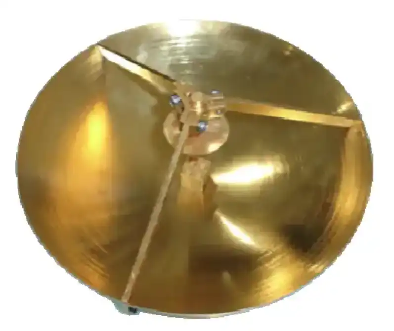
Custom feed horn and LNB coupling skills are both important. A properly sized and shaped feed horn lowers edge diffraction at the subreflector boundary and excess noise — directly improving the G/T ratio that controls how well the earth station link works. If a supplier designs their own feed networks, such as X-band feed networks for radar and satellite ground stations, they don't have to use compromises that are already on the market. Instead, they can make these parts fit the aperture geometry and operating band exactly.
For outdoor teleport and defense radar deployments, it's also important to have environmental qualification data — salt spray resistance per ASTM B117 and wind survival ratings verified through structural analysis up to 200 km/h.
Conclusion
In symmetric dual-reflector cassegrain antenna design, subreflector blockage is an inevitable structural reality. However, its effect on gain, sidelobe levels, and cross-polarization performance can be fully managed with careful planning and strict quality control during manufacturing. When buyers know how blockage geometry, aperture efficiency, and link budget margin work together, they can more objectively compare different antenna solutions based on technical factors rather than just nominal specifications.
FAQ
How much efficiency loss does subreflector blockage typically cause?
Blockage-related efficiency loss is usually less than 1% in earth station antennas with a diameter of more than 2.4 m and more than 10% in antennas with a diameter of less than 50 wavelengths. Loss amounts are different for each aperture size, subreflector diameter ratio, strut shape, and working frequency.
Can subreflector blockage be completely eliminated?
Because of the way shapes work, complete elimination is not possible in symmetric Cassegrain antenna configurations. Offset-fed designs take the subreflector out of the aperture shadow physically. This makes for almost no blockage, but it costs more to build and construct. In most business earth station uses, it is more practical to optimize the blockage ratio than to get rid of it completely.
What role does the manufacturer play in managing blockage effects?
Some of the most important factors that affect blocking are controlled by the manufacturer. These include subreflector size, surface accuracy, strut shape, and feed horn matching. When suppliers use CEM to optimize designs, keep machining tolerances low, and provide verified FAT documentation, they can give procurement teams quantitative assurance that system link budget losses due to blockages will stay within the budget.
Partner With ADM for Precision Cassegrain Antenna Solutions
With over 20 years of experience making things, ADM brings to every cassegrain antenna project ISO 9001:2015 approval, the ability to measure near- and far-field up to 110 GHz in-house, and the ability to fully customize for OEMs. Our engineering team is ready to help you with your needs, whether you need a high-gain Ka-band earth station antenna, a ruggedized radar feed assembly, or a precise research-grade reflector system. To talk about your project, email us at craig@admicrowave.com.
References
1. Ruze, J. — "Antenna Tolerance Theory — A Review," Proceedings of the IEEE, 1966.
2. Rahmat-Samii, Y. & Galindo-Israel, V. — "Shaped Reflector Antenna Analysis Using the Jacobi-Bessel Series," IEEE Transactions on Antennas and Propagation, 1980.
3. Stutzman, W. L. & Thiele, G. A. — Antenna Theory and Design, John Wiley & Sons, 2012.
4. Milligan, T. A. — Modern Antenna Design, 2nd ed., IEEE Press / Wiley-Interscience, 2005.
5. ITU-R Recommendation S.580 — "Radiation Diagrams for Use as Design Objectives for Antennas of Earth Stations," International Telecommunication Union, 2004.
6. Balanis, C. A. — Antenna Theory: Analysis and Design, 4th ed., Wiley, 2016.
YOU MAY LIKE
 VIEW MOREDouble-bend Waveguide
 VIEW MOREHigh Power Waveguide Differential Phase Shift Isolator
 VIEW MORE90° Polarized Rotary Joint
 VIEW MOREWaveguide Electric Switch
 VIEW MOREDouble Ridged Flexible Waveguide
 VIEW MOREPyramid Horn Lens Antenna
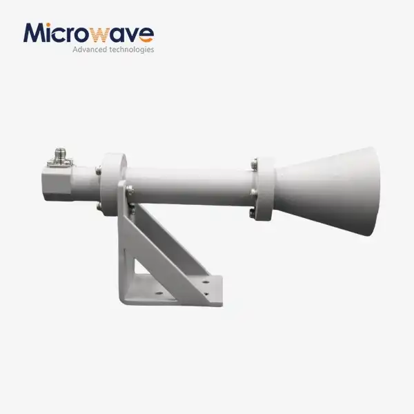 VIEW MOREDual Linear Broadband Circular Polarization Horn Antenna
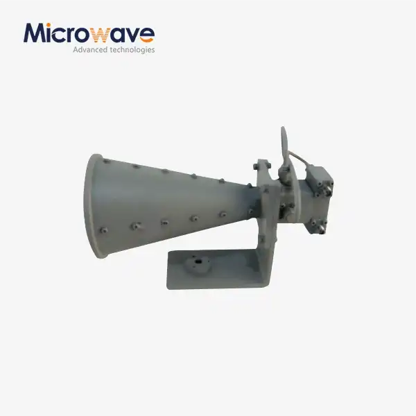 VIEW MOREDual Linear Broadband Dual Circular Polarization Horn Antenna
