





Crosstalk and Isolation Specs in Dual Channel Coaxial Rotary Joint Design
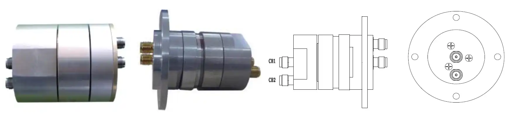
When engineers specify a dual channel coaxial rotary joint for radar, SATCOM, or defense platforms, two electrical parameters dominate every performance conversation: crosstalk and isolation. In a two-channel rotating assembly, crosstalk is the unwanted electromagnetic coupling that bleeds signal energy from one channel into the other, while isolation quantifies how effectively that coupling is suppressed — typically expressed in decibels (dB). High-performance units maintain channel isolation greater than 50 dB across the operating band, with precision-engineered models reaching beyond 70 dB. Getting these numbers right is not cosmetic; it determines whether a radar receiver captures a clean echo or drowns in its own transmit leakage.
Understanding Crosstalk and Isolation in Rotating RF Assemblies
Why Crosstalk Emerges in Confined Multi-Channel Structures
The RF path is easy to follow in a single-channel rotary joint. When you add a second coaxial channel, whether it's stacked or concentric, the mechanical frame is shared, the center wires are close to each other, and there are common ground structures. Each of these things makes a possible path for electromagnetic interaction. At X-Band frequencies (8–12 GHz) and above, even gaps of less than a millimeter in the internal shielding can cause leakage that can be measured. In a full-duplex radar, where the send signal is 60–80 dB stronger than the received echo, a poorly shielded joint working at 10 GHz could have channel isolation as low as 30–35 dB, which is very bad.
How Isolation Leads to Accurate Systems
Isolation is not just an RF statistic; it is a measure of the health of the whole system. Air Traffic Control (ATC) surveillance radars can't tell the difference between targets when the transmit and receive channels aren't separated well enough. Cross-channel leaking hurts the cross-polarization discrimination (XPD) of SATCOM On-The-Move (SOTM) devices that deal with dual-polarization signals (RHCP and LHCP). This makes it harder for data to flow through. Verified field data from radar system integrators consistently shows that the noise floor at the receiver input stage goes down by 10 dB for every 10 dB improvement in channel isolation.
Design Principles That Govern Crosstalk Suppression
Concentric Architecture and Precision Dielectric Selection
In dual channel coaxial rotary joints, the most common internal structure is a fully concentric coaxial setup, with one channel running through the center wire path and the other through the outer coaxial layer, with precision-machined dielectric bands separating them. The dielectric material, which is usually PTFE or ceramic-loaded compounds, needs to have a low dissipation factor and keep its shape when the temperature changes from -40 °C to +85 °C. Any change in the shape of the dielectric under temperature stress changes the balance of the resistance and creates a way for channels to connect.
Impedance Matching and Contact Technology
Impedance gaps between the rotor and stator are a main cause of both insertion loss and coupling between channels. Precision tolerances of less than ±0.01 mm are standard in high-quality production. This makes sure that the 50-ohm characteristic impedance is maintained through the rotating interface without any reflection. It's also important to know about the contacts. Gold-on-gold contacts make sure that there are no micro-arcing problems during spinning, which can cause noise that shows up as high crosstalk across the whole working bandwidth. Stable phase and amplitude, also known as WOW performance, must stay within ±3° and ±0.05 dB during a full 360° turn.
Frequency Range and Its Impact on Isolation Budget
The isolation budget gets smaller as the operating frequency goes up. A joint that can separate 60 dB at 2 GHz (L-Band) might only be able to do 50 dB at 18 GHz (Ku-Band) because internal coupling paths are more effective at shorter wavelengths. This is why dual-channel designs made for wideband uses usually have separate internal shapes for each channel, with Channel 1 impedance-matched for X-Band and Channel 2 designed for L-Band. This way, both channels don't have to go through the same broadband structure.
Performance Benchmarks: How Dual Channel Coaxial Joints Compare
Understanding where this component type sits relative to alternatives helps procurement teams better manage technical risk and budgets when they know where this type of component fits in comparison to other options. Here's how the main tools stack up on measures that matter for missions:
- Waveguide rotary joints are better at handling power and have lower insertion loss in narrow frequency bands, but they can't be used in multi-channel small designs. Because they are too big and can only handle one mode, they can't be used in situations where two separate signal paths need to share a rotating axis.
- Fiber optic rotary joints (FORJs) have a potentially infinite bandwidth and no RF crosstalk. However, they need electro-optical conversion steps, add latency, and can get messed up by mechanical things in the field. They are much more expensive than cable options.
- Dual-channel coaxial rotary joints are in the middle. They can handle frequencies from less than 1 GHz up to 40 GHz in standard catalog configurations. They can also send both power and data at the same time, have isolation levels above 50 dB in production units, and can rotate 10 to 50 million times under normal conditions.
The dual channel coaxial rotary joint is still the best choice for most radar, defense, and SATCOM procurement projects that need a small size, good wideband performance, and field dependability.
What Procurement Teams Must Verify Before Sourcing
Quality Control Requirements Beyond Visual Inspection
To buy these parts responsibly, you need to do more than just measure them. You need to do dynamic RF testing as well. To find the S-parameters (S11, S12, S21, and S22) while the joint is rotating under load, a Vector Network Analyzer (VNA) must be used. Cross-channel isolation checks must make sure that Channel 2 doesn't get worse when Channel 1 is used at high power. Environmental Stress Screening (ESS), which includes thermal cycling (-40 °C to +85 °C) and MIL-STD-810 vibration profiles, checks how well the product works in harsh conditions. Additional requirements for acceptance include measuring the starting torque and making sure the seals meet IP65 or IP67 standards.
Supplier Selection Criteria That Protect Program Risk
When looking for a precision rotating RF part for a mission-critical application, the production depth of the seller is just as important as the datasheet. Key requirements include proven experience in concentric coaxial machining, quality systems that can be tracked (ISO 9001:2015 certification), the ability to make changes for non-standard frequency bands or connector interfaces, and lead times that are written down and match program schedules. A lot less risk is involved in the procurement process when suppliers offer prototype evaluation units with full VNA test data before committing to production.
Installation and Long-Term Isolation Maintenance
The isolation performance in service is directly affected by how well the installation was done. If there is even a tiny bit of misalignment at the rotor interface, it causes uneven coupling between channels that can't be fixed by setting after installation. When cables are routed on the stator side, they must not put too much mechanical stress on the connection surfaces. This is because deformation of the connectors changes the resistance at the entry point and lowers return loss.
As part of regular maintenance, channel isolation should be checked again and again with a portable VNA or spectrum analyzer. This is especially important after a mechanical shock or a long period of high-rotation-speed operation. Rotational noise is caused by changes in contact resistance, which tends to get worse after 5 million turns in units with silver contacts. On the other hand, gold-on-gold contact systems keep working well after that point.
Conclusion
Crosstalk suppression and channel isolation are not extra features of a dual channel coaxial rotary joint; they are what make the part useful in any multi-signal rotating system. The isolation budget decides how sensitive a system is, how good the link is, and how reliable it is for operations. This includes everything from ATC radar to EO/IR defense weapons. Purchasing teams that know these parameters, check them with dynamic RF testing, and buy from sellers who have a history of making precision parts regularly get better results from their programs than teams that treat this part like a commodity.
FAQ
What amount of separation is good enough for radar applications?
A channel isolation of at least 50 dB across the operating band is required by most radar procurement specifications. High-performance programs, especially ones that send and receive at the same time, usually need 60–70 dB. Custom designs can achieve isolation levels above 70 dB by using better internal shielding structures and carefully made circular shapes.
Can a different frequency band be used for each channel?
Yes. Channel 1 can be tuned to X-Band (8–12 GHz) because the two channels are electrically separate, while Channel 2 works at L-Band (1–2 GHz). Each channel's internal shape is impedance-matched to its own frequency needs. This keeps performance from dropping when two bands are forced through a single broadband structure.
What makes spinning noise happen, and how can it be fixed?
Dynamic contact resistance changes and micro-arcing at the rotor-stator junction cause rotational noise. Higher-quality units use gold-on-gold contacts and controlled contact force geometry to keep the electrical path stable during the rotation cycle. This gets rid of noise spikes that would otherwise mess up sensitive receiver channels.
Can these joints handle sending both power and data at the same time?
Yes. It is common to route RF power on one channel and high-frequency data on the other. It's important to know the power rating up front, both peak and continuous wave (CW), so that the right dielectric materials can be chosen to keep the electronics from breaking down under long-term high-power conditions.
Partner with ADM for Precision Dual Channel Coaxial Rotary Joint Solutions
Every precision RF rotating interface that ADM makes is based on more than 20 years of experience in the field. We are a reliable supplier of dual channel coaxial rotary joints for defense, SATCOM, and industrial radar programs around the world. Our production is ISO 9001:2015-certified, and we offer full VNA test documentation and custom configurations that meet your frequency, connector, and environmental needs. To get detailed datasheets and sample evaluation units, email our engineering team at craig@admicrowave.com.
References
1. Pozar, D. M. — Microwave Engineering, 4th Edition, Wiley, 2011.
2. Collin, R. E. — Foundations for Microwave Engineering, 2nd Edition, IEEE Press / Wiley-Interscience, 2001.
3. IEEE Transactions on Microwave Theory and Techniques — Isolation and Coupling Characteristics of Multi-Channel Rotary Joints, IEEE, 2017.
4. MIL-STD-810H — Environmental Engineering Considerations and Laboratory Tests, U.S. Department of Defense, 2019.
5. IEC 61169-1 — Radio-Frequency Connectors: General Requirements and Measuring Methods, International Electrotechnical Commission, 2013.
6. Wadell, B. C. — Transmission Line Design Handbook, Artech House, 1991.
YOU MAY LIKE
 VIEW MOREWaveguide Switch
 VIEW MORECustom WG to Coaxial Adapter
 VIEW MORERight Angle Waveguide to Microstrip Adapter
 VIEW MOREHigh Power Waveguide Isolator
 VIEW MOREHigh Power Waveguide Differential Phase Shift Isolator
 VIEW MOREDouble Ridge Waveguide Transition
 VIEW MOREActive Limiter
 VIEW MOREAntenna Near Field Measurement Probe
