





How Much Power Can a High Power Coaxial Switch Really Handle?
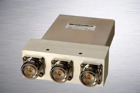
A high power coaxial switch is a specialized RF routing device engineered to direct signals through transmission lines while sustaining significant power loads — ranging from hundreds of watts to several kilowatts of continuous wave (CW), and into the megawatt range at peak. Unlike standard switches, these components incorporate robust dielectric materials, precision-machined cavities, and advanced thermal management to prevent arcing, multipaction, and contact degradation. In defense radar, satellite ground stations, and broadcast infrastructure, they are indispensable. Understanding true power capacity is the foundation of any reliable RF system design.
Understanding High Power Coaxial Switches and Their Power Handling Principles
How RF Signal Routing and Power Management Work Together
At its core, a high-power coaxial switch basically moves signals from one transmission path to another without adding a lot of loss or reflection. This is done in different ways by electrical and solid-state systems. Electromechanical types have actual contacts that are moved by a magnetic coil. This gives them great isolation and low insertion loss, usually better than 70–100 dB. PIN diodes or GaAs FETs are used in solid-state systems to make fast switching possible without any moving parts.
Managing power is mainly an issue of temperature and electricity. It is called resistive heating when RF current flows through a conductor. If that heat can't get rid of itself properly, the switch breaks down. This is why thermal management—using conductive housing materials, heat sinks, and even nitrogen pressurization in some designs—directly affects how much power a switch can handle over the course of its life.
Real-World Applications Driving Power Demands
The following B2B environments need these switches the most:
- Defense radar and electronic warfare: AESA radar systems and jamming platforms need switches that can handle high peak power pulses and fast cycling in MIL-STD-compliant conditions, and they also need to be able to fight multipaction in vacuum settings.
- Broadcast transmitter routing: TV and FM broadcasters run 24 hours a day, seven days a week at high average CW power levels. In these systems, switches have to deal with the risk of contact welding and keep the impedance stable at all times.
- Medical and scientific research: In medical and scientific studies, MRI coils and particle accelerator beamlines need very low passive intermodulation (PIM)—usually better than −160 dBc—while still being able to handle a lot of pulse power without messing up important measurement data.
These examples of program settings show why power handling is never just a single number. It always works in a certain frequency range, duty cycle, thermal load, and connector interface.
Key Factors Determining How Much Power a High-Power Coaxial Switch Can Handle
Electrical, Thermal, and Material Parameters
A high power coaxial switch’s real power limit is set by a number of factors that affect each other. Procurement engineers should look at these parameters as a whole, not separately. Things that really matter in high-power deployments are these:
- CW and peak power ratings: A switch that can handle 5 kW CW at 1 GHz might only be able to handle 2 kW at higher frequencies. IEEE transmission line studies have shown that as frequency goes up, skin depth goes down, resistance goes up, and the dielectric breakdown margin gets smaller.
- Insertion loss and VSWR: Switches with VSWR less than 1.15:1 and insertion loss less than 0.05 dB generate very little heat inside. Higher loss speeds up thermal runaway, which is one of the main reasons switches fail too soon in high-duty-cycle settings.
- Contact materials and plating: Beryllium copper contacts that are gold-plated offer better conductivity and fatigue protection over millions of actuation cycles. To keep the signal's integrity, contact resistance should stay below 15 mΩ for the full rated lifespan.
- Connector interface design: EIA flanges, which come in sizes from 7/8" to 6-1/8", have a much larger contact surface area and can handle higher dielectric voltages than N-type or SMA connectors. This makes them the best choice for systems that use more than one kilowatt.
- Thermal dissipation architecture: The thermal dissipation design includes precisely machined holes made of aluminum or brass that are sometimes compressed with dry nitrogen. These holes increase the dielectric strength and stop corona discharge at high voltages.
These factors affect each other directly. No matter how good the contact material is, if the switch doesn't have good thermal management, it will still fail under long-term load. When procurement teams look at them all together, they get the best picture of how reliable things really are in the field.
Comparing High Power Coaxial Switches: What Sets the Limits?
Electromechanical vs. Solid-State: A Performance Trade-Off
Electromechanical switches are the most common type used in high-power situations because they can handle CW ratings of many kilowatts, have low insertion loss, and keep high isolation across wide bandwidths. Their weakness is mechanical wear; a well-kept unit can usually handle 1 to 5 million activation cycles before the contact resistance starts to decrease in a way that can be measured.
Solid-state switches can switch almost infinitely and have response times in microseconds, but they can only handle a lot less power. They work best in situations with fast switching and modest power, not long-term high-power routes.
The type of actuator is an important difference in electric designs. Latching switches stay in place without constant coil power, which keeps the actuator from getting too hot, which is a big benefit for use in vacuums or space. If the power goes out, failsafe switches go back to their original state. This gives transmitters the built-in protection logic that many defense and broadcast applications need.
Overcoming Common Issues and Enhancing Power Handling in Coaxial Switches
Thermal Buildup, Contact Erosion, and Cold-Switching Discipline
Sustained high-power operation introduces several degradation mechanisms. Thermal buildup is the most common. Using infrared thermography during plant quality testing, where temperature rise is usually limited to +35°C above ambient, finds hotspots that would not be seen until the product fails in the field.
Contact erosion and switching discipline go hand in hand. Most high power coaxial switches are only meant to be used for cold switching, which means that RF power has to be turned off before the switch can work. When high power levels are used for Hot switching, arcing, contact cracking, and rapid device damage occur. Live-signal switching can only be done with certain arc-suppressed or solid-state units.
Manufacturers who care about quality put these devices through strict qualification procedures. These include dielectric withstand voltage (Hi-Pot) testing, full-frequency VNA sweeps to confirm isolation and insertion loss, PIM testing at carrier-grade thresholds, and mechanical life-cycle endurance testing that goes over one million cycles. These tests are the proof that shows the difference between an effective high-power RF switch and one that breaks down under load.
Procurement Guide: Selecting and Buying High Power Coaxial Switches
A Practical Checklist for B2B Sourcing Teams
Before sending out an RFQ, buying experts should make sure that the following are in line with the needs of their system design for high-power coaxial switches:
- Power rating at operating frequency: Check both the CW and peak ratings at the frequency band you're interested in, not just the highest-rated frequency point.
- Connector and interface compatibility: Check to see if heavy-duty interfaces like EIA flanges, 7/16 DIN, or others are needed based on the power levels in the system.
- Switching speed and duty cycle: Most electromechanical systems switch in 10–50 ms, and they stay in the solid state for microseconds. This should match the switching needs of your system.
- Latching vs. failsafe: Choose based on whether your system needs to be positioned safely in case the power goes out.
- Certifications and documentation: For defense and aircraft purchases, you must have ISO 9001 compliance, RoHS paperwork, and MIL-STD traceability.
- OEM customization capability: For many mission-critical deployments, changing frequency ranges, non-standard flange measurements, or custom housing configurations are needed. Make sure that your supplier can handle this.
Integration risk is greatly reduced when working with a maker that provides prototyping, technical support, and global shipping assistance. This is especially true for OEM buyers who are putting together large numbers of RF subsystems.
Conclusion
The technical problem of how to handle power in a high power coaxial switch has many variables. In the real world, efficiency is affected by frequency, contact material, thermal design, connection interface, and switching discipline. In high-power situations, electromechanical systems are most common. At lower microwave frequencies, CW ratings often hit 5 kW or more. When procurement engineers look at all of these factors together instead of just looking at the wattage, they can make decisions about where to buy things that will last under operational stress. If you buy the right switch from a reputable manufacturer and follow the instructions carefully, it will last for years.
FAQ
Can a high-power RF switch perform hot switching?
In most cases, no. For most electrical systems, the RF power has to be turned off before the mechanism can be moved. Arcing and immediate contact damage happen when hot switching occurs. Live-signal swapping can only be done with arc-suppressed or solid-state units.
How does frequency affect the power rating?
As frequency goes up, power handling goes down. At 1 GHz, a switch that can handle 10 kW at 100 MHz might only be able to handle 2 kW because of higher resistive losses and smaller dielectric breakdown gaps.
What is the lifespan of an electromechanical high-power switch?
A unit that is well taken care of can usually last between 1 and 5 million mechanical cycles. Electrical service life depends a lot on how well you use cold-switching. Accidental hot-switching events drastically shorten service life.
Why are EIA flanges preferred over N-type at high power?
EIA flanges have a rigid air-dielectric link with a lot more contact surface area than N-type connections. This means they can handle higher voltages and heat better.
Partner with ADM for Reliable High Power Coaxial Switch Solutions
Every part that ADM makes is based on more than 20 years of experience making precise RF parts. As a reliable high power coaxial switch supplier, we offer products that are ISO 9001-certified, RoHS-compliant, OEM-customizable, and include full technical support. Our engineering team is ready to help you, whether you need a basic setup or a solution that is made just for you for defense, satellite, or industrial use. You can talk about your needs right away by emailing craig@admicrowave.com to discuss your requirements.
References
1. Pozar, D. M. Microwave Engineering, 4th ed. — John Wiley & Sons, 2011.
2. Collin, R. E. Foundations for Microwave Engineering, 2nd ed. — IEEE Press / Wiley-Interscience, 2001.
3. IEEE Std 287-2007 — IEEE Standard for Precision Coaxial Connectors (DC to 110 GHz). IEEE, 2007.
4. RF and Microwave Power Amplifier and Transmitter Technologies — High Frequency Electronics, 2005.
5. MIL-PRF-3928 — Performance Specification: Switches, Radio Frequency Coaxial. U.S. Department of Defense, 2020.
6. IEC 61169-1 — Radio-Frequency Connectors, Part 1: Generic Specification. International Electrotechnical Commission, 2013.
YOU MAY LIKE
 VIEW MOREWaveguide Twist
 VIEW MORECustom WG to Coaxial Adapter
 VIEW MOREWG Transition
 VIEW MOREWaveguide Single Channel Rotary Joint
 VIEW MOREWaveguide Flange Gasket
 VIEW MOREMMDS Transmitting Antenna
 VIEW MOREWideband Double-ridged Horn Antenna
 VIEW MORELadder Membrane Square Dual Circular Polarization Horn Antenna
