





Horn Lens Antenna Gain Optimization for RF Applications
Horn lens antenna gain optimization is essential for maximizing the efficiency and range of RF communication systems. The horn lens antenna combines a feed horn with a dielectric or shaped lens structure to focus electromagnetic energy into a narrow beam, thereby increasing directional gain. Optimizing this gain involves careful selection of low-loss materials, precise lens geometry, and accurate feed alignment to minimize signal attenuation and reflection losses. Engineers working with satellite communications, radar systems, and wireless backhaul applications rely on these techniques to achieve the high-performance standards demanded by mission-critical operations, ensuring reliable signal transmission across extended distances.
Understanding Horn Lens Antenna Gain
Compared to an isotropic reflector, antenna gain shows how well an antenna sends radio frequency energy in a certain direction. Higher gain means that the information is more concentrated, the contact range is longer, and interference from other sources is lessened. When designing RF systems, where signal integrity and power efficiency have a direct effect on how well they work, this metric is very important.
Horn Lens Antenna Working Principle
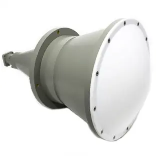
A feed horn makes electromagnetic waves, and a dielectric lens forms and focuses these waves into a coherent beam. This is how the horn lens antenna architecture works. The lens element, which is usually made of polyethylene or PTFE, bends the wavefront that comes out of the horn opening, focusing the beam to make it more focused. This design cuts down on side waves and excess losses, which makes the antenna gain better overall than with regular horn antennas working by themselves.
Key Design Elements Influencing Gain
The way horn lens antennas work is affected by a number of things. How well a lens focuses energy depends on its geometry, which includes its curvature radius and thickness. Signal reduction and phase accuracy are directly affected by features of the material, like its dielectric constant and loss tangent. The initial wavefront distribution is affected by the size and angle of the flare of the feed horn. Precise integration between the horn and lens reduces reflection losses at the interface. When procurement teams know these factors, they can choose parts that meet strict performance standards for defense, aircraft, and telecom uses.
Importance for Procurement Decisions
When procurement workers look at antenna systems, they need to think about how the gain specs match up with the needs of the whole system. Antennas with a gain of more than 20 dBi are better for long-distance transmission or high-resolution radar images. The decision process is also affected by things like budget, room, and standards for environmental longevity. Purchasing managers can ask sellers about customisation options, performance evaluation processes, and compliance with quality standards like ISO 9001 and RoHS if they understand the technical foundations of gain optimisation.
Challenges in Optimizing Horn Lens Antenna Gain
To get the best gain performance, you have to get past a lot of technical problems that come from material science, industrial accuracy, and environmental factors. Signal loss due to material absorption is still a problem, especially at millimeter-wave frequencies where dielectric loss tangent values are more important. It is possible to measure absorption in even high-quality lens materials, which lowers effective gain and system efficiency.
Alignment and Assembly Precision
A common reason why performance drops is that the feed horn and lens assembly of a horn lens antenna are not lined up correctly. Wavefront distortion can be caused by even small changes in angular or axial movement. This can raise the amounts of sidelobes and lower the on-axis gain. Alignment mistakes can get worse because of manufacturing tolerances in mechanical attachment gear and thermal growth during use. A case study from an upgraded satellite ground station showed that a misaligned feed horn by 0.5 degrees caused a 2.1 dB loss of gain at Ka-band frequencies, which had a direct effect on link margin and data throughput capacity.
Environmental and Operational Factors
Changes in temperature can affect both the dielectric constant of lens materials and the stability of antenna structures' dimensions. Rain and snow can make outdoor setups difficult because they can change the dielectric properties of radome covers and lens surfaces. When mounting hardware or nearby structures get in the way, they cast shadows that change the way radiation patterns work. To keep the gain performance stable over the system's operational lifecycle, these environmental factors must be carefully thought through during system design and installation.
Manufacturing Variability and Bandwidth Constraints
The production process changes the lens surface finish, the homogeneity of the material, and the size of the feed horn, all of which affect the stability of the gain across production runs. Frequency bandwidth limits are caused by the way dielectric materials scatter light and how lens refraction changes with frequency. Maintaining uniform gain across the operational spectrum is especially hard for wideband systems that use more than one octave. This usually means making design adjustments or using multiple antenna configurations.
Proven Techniques for Horn Lens Antenna Gain Optimization
To fix gain bottlenecks, you need a methodical approach that combines advanced materials engineering, precise manufacturing, and strict testing rules. These methods make sure that antenna systems meet strict performance requirements in a wide range of working circumstances.
Material Selection and Lens Design
High-gain antenna designs are built on dielectric materials with low loss. Modern foam-based dielectrics and specialized plastics have loss tangent values below 0.001 at microwave frequencies. This means that signals are weakened less while the structure stays strong. Ray-tracing techniques and electromagnetic modelling tools are used in lens curvature calculations to get the best focal length and aperture performance. Graduated lens profiles and zoned structures can improve performance over a wider bandwidth while reducing aberrations that lower gain at angles other than the focal plane.
Feed Horn Alignment and Interface Engineering
Critical positioning tolerances are kept between feed components and lens elements using mechanical alignment fixtures and precise assembly techniques. Field calibration can be used to account for differences in manufacturing with the help of adjustable fixing systems that let you control placement down to the micrometre level. When anti-reflection coatings are put on lens surfaces, they cut down on interface reflections that cause standing waves and insertion loss. At the feed change, impedance matching structures keep return loss to a minimum. This makes sure that the antenna system gets the most power possible.
Simulation-Driven Design Optimization
Electromagnetic simulation tools like ANSYS HFSS and CST Microwave Studio let you model horn lens antenna performance in great depth before making a physical prototype. These programs can guess how much gain, how much impedance, and how pure the polarisation will be across a wide range of frequencies and weather factors. Parametric optimisation algorithms look at a lot of design variables to find the best configurations that maximise gain while also meeting size, weight, and production requirements. Simulation confirmation cuts down on development times and boosts trust in predicted performance, which is especially helpful for custom designs that are used in unique situations.
Field Testing and Calibration Protocols
Thorough testing in controlled environments confirms that the design works and finds ways to make it better. Antenna measurement centers with precise positioning tools and measured reference sources describe the features of radiation patterns, gain magnitude, and polarization. At Advanced Microwave Technologies Co., Ltd., our 24-meter microwave darkroom has the right measurement distance for accurate far-field characterization from 0.5 GHz to 110 GHz. The Antenna Plane Near and Far Field Measuring Recombination Chamber lets you look closely at both the near-field distribution and the far-field behaviour. This helps with optimization efforts that make sure production units meet gain goals.
Environmental Parameter Optimization
The best way to position the boresight and reduce the effects of atmospheric attenuation is to mount the antenna so that it faces the signal routes. Radome selection uses materials and shapes that are best for certain frequency bands to protect the environment while minimizing RF loss. Putting shielding around antenna placements cuts down on multipath interference and electromagnetic compatibility problems that lower the antenna's useful gain. Thermal management strategies keep lens materials and electronic parts working at stable temperatures, so they keep working the same even when the weather changes.
Comparison with Other Antenna Types for Gain Optimization
To choose the right antenna design, you have to weigh the pros and cons of gain performance, physical limitations, cost, and operational freedom. Each technology has its own benefits that make it better for certain types of applications.
Parabolic Reflector Antennas
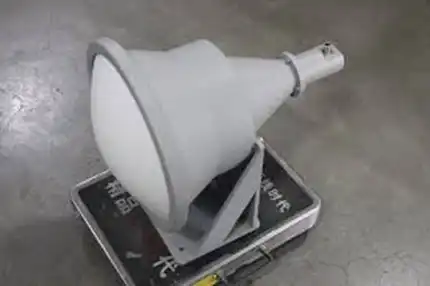
Parabolic dish antennas work great in situations that need maximum gain. They can regularly reach 30 to 50 dBi in installations for radio astronomy and satellite communication. The shape of the reflector focuses the waves that hit it very well, thanks to well-established design and production methods. But these systems need big mounting frames to hold up their big openings, which makes them hard to use in places with limited room and for mobile apps. Wind loading and structural rigidity requirements make installation more expensive and make it harder to move around than with small horn lens antenna designs.
Dielectric Lens Antennas
Pure dielectric lens antennas that don't have horn lines are easier to integrate mechanically and have lower metal losses. You can change the beam characteristics and frequency response by choosing the right material and shaping the lens. These designs work especially well at millimeter-wave frequencies, where waveguide parts get smaller and it's harder to make them with tight specs. If there are no resonant structures, the operational bandwidth can be increased, but bigger lens diameters and more material are often needed to get the same gain as horn lens antenna hybrids.
Phased Array Systems
Phased arrays that are controlled electronically allow for dynamic beam positioning without any mechanical movement. This makes it possible to quickly track targets and adjust interference cancellation. Individual element control lets you change the strength distribution and use more than one beam at the same time. Each radiating part needs its own phase shifters and control circuits, which makes things more complicated and costs more. As the array gets bigger, it gets harder to control the heat and use more power. Phased arrays are most cost-effective when the ability to change beams makes them worth the investment. Horn lens antennas often have better cost-to-performance ratios for fixed-beam uses that need modest gain.
Application-Specific Selection Criteria
For defense radar systems, horn lens antennas are useful because they are tough, work reliably, and can't be attacked electronically. Satellite ground stations have to balance the need for gain with the limitations of transport and placement. This is where small horn lens antenna designs come in handy. Backhaul links for telecommunications that serve point-to-point connections like horn lens antenna options because they are reliable and cost-effective for gain bands of 18 to 30 dBi. Research groups that study propagation like these antennas because they have well-defined patterns and can be customized to fit their needs.
Conclusion
In conclusion, to get better RF performance, optimizing horn lens antenna gain means finding the right balance between material science, mechanical accuracy, and electromagnetic design principles. Procurement professionals can choose systems that meet strict application requirements if they know about the technical challenges and tried-and-true optimization techniques. The comparison with other antenna architectures makes the trade-offs that go into choosing a technology clear. Strategic relationships with suppliers, especially those that let you customise products and offer full technical support, pay off in the long run through reliable performance and quick service.
FAQ
1. What frequency ranges are typically covered by horn lens antennas?
Horn lens antennas work in both microwave and millimeter waves. Depending on the form, they usually work at frequencies between 1 GHz and 110 GHz. Higher frequency units are used for Ka-band and V-band communications, while lower frequency units work with L-band and S-band satellite communications. New 5G millimeter-wave bands and trial systems that work above 100 GHz need special designs to work with them. It is possible to design custom frequency coverage to fit the needs of a system and the available spectrum.
2. How does polarization affect antenna gain and signal quality?
Matching the polarisation of the sending and receiving antennas makes signal transfer more efficient and reduces insertion loss as much as possible. In dual-polarized systems, cross-polarisation separation decides how well they can handle interference from orthogonal polarisation channels. When using linear polarization, things need to be perfectly lined up. With circular polarisation, on the other hand, pointing is less sensitive, but there is a 3 dB theoretical loss. Specifications for polarization purity make sure that there is little coupling between orthogonal modes. This keeps signal quality high in advanced modulation schemes that are sensitive to phase distortion.
3. Can horn lens antennas be customized for 5G networks?
Customized antenna systems that deal with specific frequency bands, coverage patterns, and mounting issues are helpful for setting up 5G infrastructure. For 5G millimeter-wave frequencies like 24 GHz, 28 GHz, and 39 GHz bands, horn lens antenna designs can be made better. Customisation includes changing the radiation pattern to meet the needs of different coverage areas, mechanically integrating with small cell casings, and operating on multiple bands to support spectrum aggregation. Our tech teams work with telecom clients to create custom solutions that meet 5G performance goals for network density, throughput, and delay.
Partner with ADM for Optimized Antenna Solutions
Choosing the right horn lens antenna supplier is the first step to getting the most out of your RF system. Advanced Microwave Technologies Co., Ltd. makes custom high-gain antenna solutions and offers full technical support and strict quality control. Our microwave lab is 24 meters long and can measure up to 110 GHz, so we can be sure that every product meets the highest standards. Our experienced team provides quick and helpful service throughout the whole procurement process, whether you need to find large quantities, make custom configurations, or need delivery as soon as possible. Contact craig@admicrowave.com to talk to one of our engineering experts about your needs and find out why we are the best horn lens antenna maker for tough RF uses. We can do precise manufacturing, ship products all over the world, and have a track record of reliability. Get your thorough quote today, and you can feel good about moving forward with your communication tools.
References
1. Balanis, Constantine A. Antenna Theory: Analysis and Design, 4th Edition. John Wiley & Sons, 2016.
2. Milligan, Thomas A. Modern Antenna Design, 2nd Edition. IEEE Press, 2005.
3. Stutzman, Warren L., and Gary A. Thiele. Antenna Theory and Design, 3rd Edition. John Wiley & Sons, 2012.
4. IEEE Standard 145-2013. IEEE Standard for Definitions of Terms for Antennas. Institute of Electrical and Electronics Engineers, 2013.
5. Olver, A. D., et al. Microwave Horns and Feeds. IEEE Press, 1994.
6. Love, A. W. Electromagnetic Horn Antennas. IEEE Press, 1976.
YOU MAY LIKE
 VIEW MOREIndustrial Microwave Isolator
 VIEW MORECustom WG to Coaxial Adapter
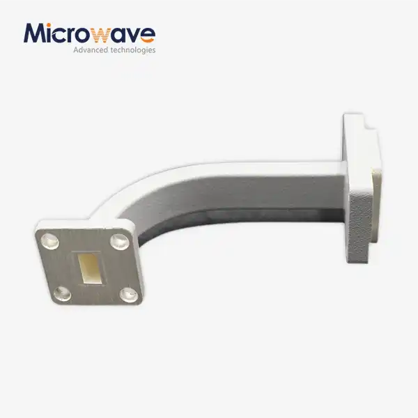 VIEW MOREWaveguide E Bend
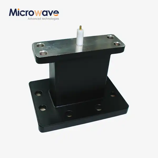 VIEW MOREEnd Launch Waveguide to Microstrip Adapter
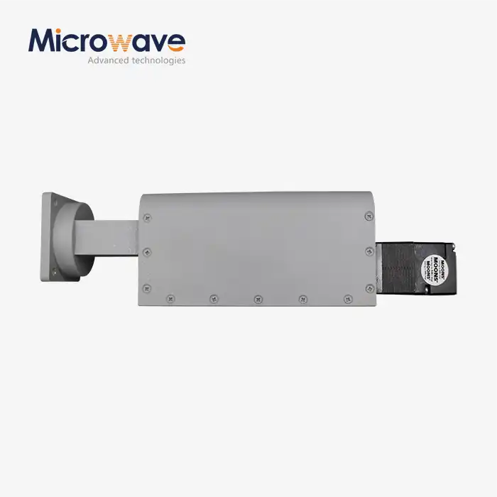 VIEW MOREWaveguide Offset Short
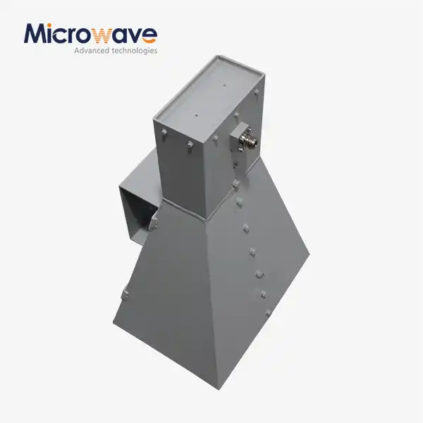 VIEW MOREWideband Double-ridged Horn Antenna
 VIEW MOREConical Circular Polarization Horn Antenna
 VIEW MOREPlanar Spiral Antenna
