





Microwave Bandpass Filter Applications in RF Systems
Microwave bandpass filters play an indispensable role in modern RF systems, enabling precise frequency selection and signal integrity across telecommunications, aerospace, defense, and scientific research. Among the various filter architectures available, WG bandpass filters stand out by leveraging waveguide technology to deliver exceptional performance in high-frequency and high-power environments. These filters allow only desired frequency bands to pass while rejecting unwanted signals, making them critical for applications ranging from satellite communications to radar systems where signal purity directly impacts operational effectiveness.
Understanding WG Bandpass Filters in RF Systems
What Are WG Bandpass Filters?
WG Bandpass Filters use the way electromagnetic waves behave in metal or insulator waveguides to screen them. Waveguide structures, unlike flat technologies like microstrip filters, keep electromagnetic energy inside sealed channels. This lowers radiation losses and makes them work better at microwave and millimeter-wave frequencies. The filters work by making resonant cavities or iris-coupled sections that let certain frequency bands pass through while reflecting others.
Core Design Parameters
When looking at waveguide filters, their success is based on a number of scientific parameters. Insertion loss is a way to measure how much a signal is weakened within the passband. It usually ranges from 0.1 dB to 1 dB, but this can change depending on frequency and design complexity. Quality factor (Q) shows how selective the filter is and how much energy it can store. Waveguide designs often get Q values higher than 5,000 because they are made of low-loss metal. Bandwidth tells the filter what range of frequencies it can pass. Depending on the application, the bandwidth can be changed from narrowband (fractional bandwidth less than 1%) to wideband (fractional bandwidth more than 10%). Normal working frequencies range from 1 GHz to more than 110 GHz, which includes L-band and W-band uses.
How They Compare to Alternative Filter Technologies?
Microstrip and cavity resonator filters are very different from waveguide filters in a basic way. Small and inexpensive microstrip filters made on printed circuit boards have a higher insertion loss and can only handle a limited amount of power, so they are mostly useful for low-power business uses. At higher frequencies, cavity filters take up a lot of space compared to waveguide solutions, but they are very selective and can handle a moderate amount of power. When low insertion loss, high power capacity, and thermal stability are needed, waveguide filters are the best choice. This is especially true above 10 GHz, where waveguide dimensions become practical and competing technologies experience rising losses.
Engineers can correctly model how waveguide filters will work before they are built using advanced computer tools like finite element method (FEM) and method of moments (MoM) software. These computer methods find the best iris measurements, coupling factors, and resonator spacing. This speeds up development and makes sure that the first design works. At Advanced Microwave Technologies Co., Ltd., we use simulation tools and our 24-meter Microwave Darkroom testing center to make sure that our waveguide components meet strict military and defense standards for filter performance across the 0.5 GHz to 110 GHz spectrum.
Key Applications of WG Bandpass Filters in RF Systems
Telecommunications and 5G Infrastructure
Bandpass filters are very important in the telecommunications industry for managing frequency spectra that are too crowded. As 5G networks grow into millimeter-wave bands (24 GHz to 40 GHz and beyond), waveguide filters help separate channels and keep neighboring frequency assignments from interfering with each other. Base station equipment, especially in cities with lots of signals, benefits from waveguide designs that have low insertion loss. This keeps valuable transmit power and receiver sensitivity.
Satellite ground stations are another important part of telecommunications. For these facilities to work, they need filters that can handle high amounts of RF power and keep the signal's integrity over long transmission lines. Installing WG Bandpass Filters in both the uplink and downlink chains makes sure that the signals are sent correctly. This helps with high-definition video sharing, broadband internet services, and emergency contact networks in rural areas.
Military and Aerospace Systems
Defence contractors and aerospace integrators choose waveguide filters for radar systems, electronic warfare equipment, and navigation platforms that have to work reliably in harsh conditions. Airborne radar systems need filters that work reliably in temperatures ranging from -55°C to +125°C, can handle vibration and shock, and can separate frequencies precisely so targets can be found in a lot of noise.
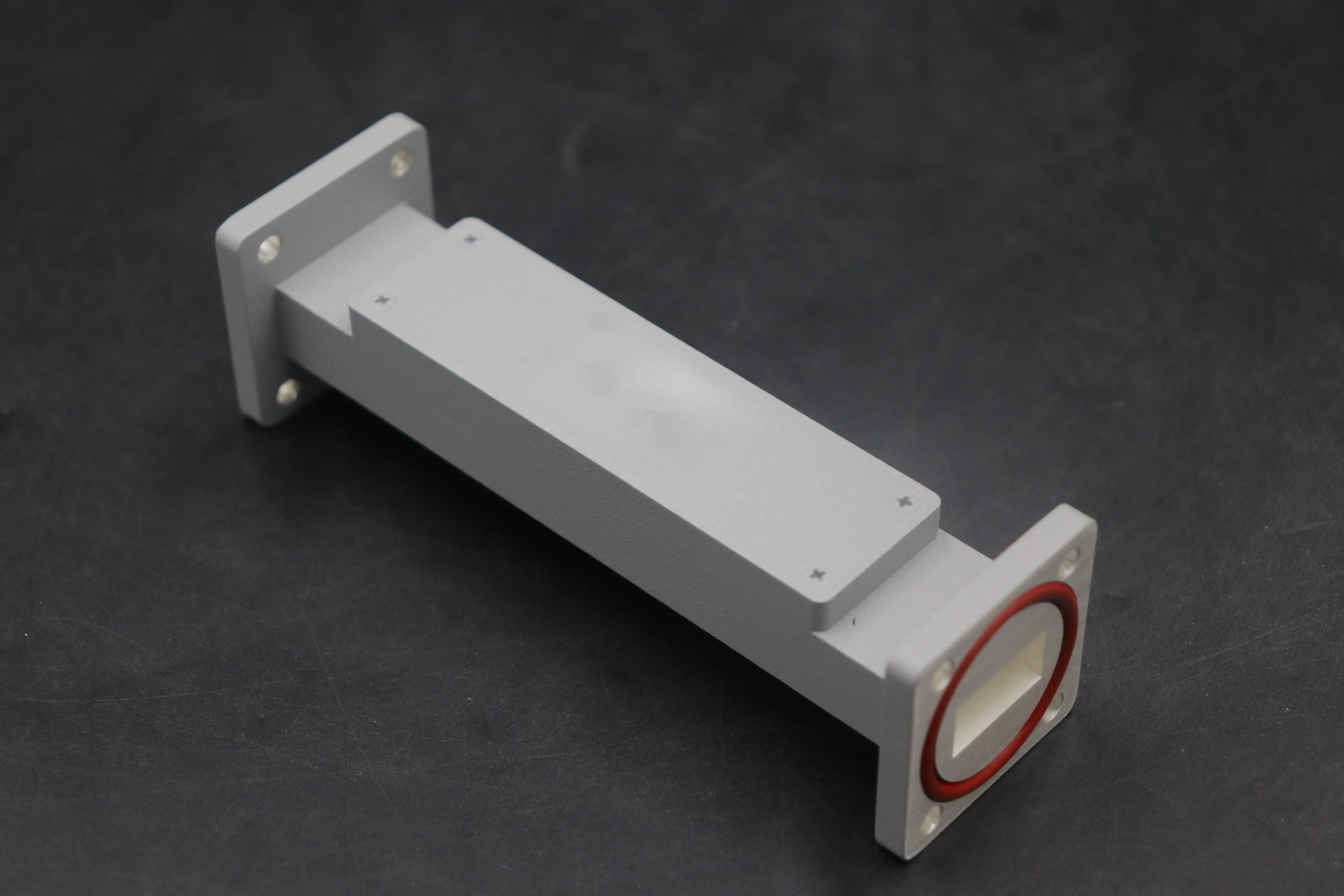
Tunable waveguide filters are used in electronic countermeasure systems to quickly switch between frequency bands. This lets them respond to changing threats in real time. For these uses, custom filter designs are often needed with certain passband features, rejection depths greater than 60 dB, and ruggedised mechanical construction that meets MIL-STD standards. Advanced Microwave Technologies' engineering team works closely with defense OEMs to create custom waveguide solutions that fit into complicated RF architectures without any problems. These solutions are backed by ISO 9001:2015 quality procedures and detailed paperwork for tracking them.
Industrial and Scientific Instrumentation
Spectrum analysers, signal generators, and equipment for characterising materials are all types of equipment that use waveguide filters in research labs and commercial measurement systems. Applications that use high frequencies for sensing, like plasma diagnostics, atmospheric monitoring, and accelerator beam diagnostics, need filters that keep the signal integrity while removing out-of-band noise.
Weather radars that work in the X-band and Ku-band frequencies use waveguide filters to separate the echoes of rain and snow from ground clutter and other signals. The thermal stability of the filters makes sure that they work the same way even when the temperature changes. This keeps the measurements accurate for long periods of time. Waveguide technology is naturally strong, so these kinds of setups don't need as much upkeep and can last longer than twenty years in the field.
WG Bandpass Filter vs. Alternative Filter Technologies
Performance Comparison Across Key Metrics
Often, insertion loss is what makes the difference between two filter methods. When the frequency is above 10 GHz, WG Bandpass Filters usually have insertion losses below 0.5 dB. On the other hand, microstrip versions may have losses above 2 dB because of wire and dielectric losses. In cascaded systems, where multiple filters add up losses that have a direct effect on link costs and system range, this difference becomes very important.
When you compare quality factors, you can see that waveguides are better at selectivity. When metal waveguide resonators are not loaded, they can reach Q values of 10,000 or higher, which lets them have steep filter edges and great nearby channel rejection. Microstrip designs rarely go above a Q of 200, while dielectric resonator filters have a moderate Q (usually 1,000 to 5,000) and are smaller. Higher Q means smoother changes between the passband and the stopband, which lets you use the spectrum more efficiently in places with a lot of frequencies.
In high-power situations, WG bandpass filter solutions are differentiated by their ability to handle power. Standard rectangular waveguide filters can handle steady power levels of more than 1 kilowatt, and some versions can handle tens of kilowatts. This ability comes from the shape of the waveguide, which spreads electromagnetic fields over bigger areas than lumped or flat structures. This keeps voltage breakdown and heat damage from happening.
When to Select Waveguide Solutions?
When users need frequencies above 8 GHz, steady power above 100 watts, or insertion losses below 1 dB, waveguide bandpass filters are the best choice. Waveguide filters are often used in military radar emitters, satellite communication payloads, and high-performance test equipment, even though they take up more space and cost more per unit. The investment was well worth it because the waveguide filter works better and lasts longer.
On the other hand, microstrip or ceramic filter technologies may be cheaper for commercial uses that operate below 6 GHz and use less than 10 watts of power. The choice depends on finding the right balance between performance needs and size, weight, and budget limits. This is something that procurement professionals need to think about as a whole, instead of just optimizing one parameter at a time.
Procurement Guide for WG Bandpass Filters
Selecting Qualified Suppliers
When picking a WG Bandpass Filter manufacturer, you need to look at more than just the specs. Certification titles are the first sign of a supplier's skills. Being certified with ISO 9001 shows that you care about quality management systems, and being certified with RoHS shows that you care about the environment. These are both basic requirements for global buying. Defense companies should make sure that suppliers know how to follow military standards and can give thorough test results that can be tracked back to NIST-certified measuring systems.
Customisation ability is often a good indicator of how well a provider can meet specific needs. Off-the-shelf filters work with standard frequency ranges, but custom solutions are often needed for mission-critical systems. When a manufacturer does its own design, prototyping, and testing, it speeds up the development process and makes sure that the design is suitable for production from the idea stage to the finished product. Our integrated engineering method at Advanced Microwave Technologies includes simulations, fast prototyping, and validation testing in our 110 GHz-capable lab. This lets us deliver custom waveguide assemblies that are optimised for specific RF designs on short notice.
Navigating the Ordering Process
Standard waveguide filters usually have lead times of four to eight weeks. Custom designs, on the other hand, can take twelve to sixteen weeks, depending on how complicated they are and how many prototypes need to be made. Early on in the system development process, procurement pros should talk to providers to make sure that delivery plans are in line with integration goals. Price cuts are often possible when you commit to buying a certain number of units. Usually, there are breaks in the price at 10, 50, and 100 units. This makes talking about production planning during the first meeting useful.
Waveguide filters have different price ranges that depend on the material chosen, how hard it is to machine, and how many tests need to be done. Copper or metal housings are more expensive than aluminium ones, but performance may be different in high-power situations. Plating something with silver or gold costs more, but it improves conductivity and corrosion resistance, which makes it last longer in harsh environments. When you know about these trade-offs, you can make smart buying choices that are based on the total cost of ownership instead of just the unit price.
When buying filters, they should come with detailed technical paperwork. For system integration, it's important to have detailed datasheets that list S-parameters for a range of temperatures, mechanical drawings that show the sizes of the interfaces, and insertion/return loss test data. Suppliers with a good reputation give simulation files in common forms (Touchstone S2P, HFSS models) that make design evaluation faster in customers' system architectures.
Best Practices for Implementing WG Bandpass Filters
Installation and System Integration
The function of a WG Bandpass Filter is directly affected by how well it is installed. To keep concentricity within tight limits (usually 0.002 inches), flange alignment must be maintained. If it doesn't, mode change and higher return loss will happen. Manufacturers should tell you how much torque to use on fixing screws so that the gaskets are compressed evenly, and the flanges don't twist. Putting RF absorber material on the outside of filters stops unwanted resonances in equipment racks that are very close together.
Impedance matching at the interfaces of filters reduces reflections that hurt the efficiency of the system. The characteristic impedance of a standard waveguide is about 500 ohms. However, transitions to coaxial lines, which have an impedance of 50 ohms, need to be carefully planned. Our team offers impedance-matched transitions as fully assembled units, which cuts down on mistakes made in the field and guarantees that all production units have the same electrical performance.
Maintenance and Troubleshooting
Waveguide filters don't need much upkeep, but they do benefit from being checked every so often. A visual inspection should find any rust, damage, or contamination that might affect how well it works. Pay close attention to the connector pins and alignment features because wear in these areas causes mechanical error that lowers the accuracy of the electrical signal.
Measurements taken with a network analyser to check performance show that filter features stay within specs. By keeping an eye on insertion loss and return loss over time, you can spot degradation before it affects how the system works. Changes in the center frequency or bandwidth could mean that there is mechanical stress, effects from changing temperatures, or moisture getting in. These are all problems that need to be fixed to keep the mission from failing.
Methodical isolation methods keep you from making the wrong diagnosis when you're fixing system problems with waveguide filters. By quickly replacing suspect filters with known-good ones, you can quickly see if the filter is causing the problems you're seeing. Using thermal imaging during high-power testing can show hotspots that mean poor contact resistance or internal arcing. This helps repair workers focus on fixing the causes instead of just fixing the symptoms.
Conclusion
In conclusion, when frequency sensitivity, low insertion loss, and high power handling are very important in RF applications, WG bandpass filters work better than any other filter. These precise parts make signal processing reliable in a wide range of applications, including telecommunications infrastructure, defense radar systems, and scientific instruments. Engineers and sourcing workers can find the best options for their specific needs if they understand waveguide filter concepts, application settings, and procurement factors. Working with skilled manufacturers that offer full customisation, strict quality controls, and quick expert help is the best way to make sure that the system works well and lasts a long time. As the need for frequency keeps going up toward millimeter-wave bands and power needs get higher, waveguide filter technology will still be important for next-generation RF systems to complete their missions.
FAQ
1. What frequency ranges do WG bandpass filters typically cover?
WG Bandpass Filters work well from about 1 GHz to 110 GHz and higher, with the frequency bands they work in depending on the size of the waveguide. Larger waveguide cross-sections are used for lower frequencies like L-band and S-band, while sub-millimeter structures are used for millimeter-wave applications. As the needs of the system dictate, custom designs can meet specific frequency assignments.
2. How does insertion loss compare between waveguide and microstrip filters?
When compared to microstrip filters, WG Bandpass Filters always have lower insertion loss, especially above 10 GHz. Waveguide insertion losses are usually less than 0.5 dB, but at the same frequencies, microstrip designs often have losses over 2 dB. This benefit comes from the fact that the waveguide's sealed shape reduces radiation losses and conductor resistance effects that are common in flat technologies.
3. Can waveguide filters be customized for specific applications?
One of the best things about WG Bandpass Filter technology is that it can be customized. Custom designs are often made by companies like Advanced Microwave Technologies to fit specific frequency plans, bandwidth needs, power handling requirements, and mechanical interface limitations. Custom solutions can handle unique environmental conditions, integration limits, and performance requirements that can't be met by off-the-shelf products. They can be used for a wide range of purposes, from satellite payloads to defense electronic warfare systems.
Partner with ADM for Your WG Bandpass Filter Needs
Advanced Microwave Technologies Co., Ltd can help you with your toughest RF system problems because they have over twenty years of experience making microwave components. Defense contractors, telecommunications integrators, and research institutions all over the world use our ISO 9001:2015-certified manufacturing processes and RoHS-compliant waveguide bandpass filter solutions. Our technical team can provide standard waveguide components or fully customized filter assemblies that are designed to your exact specs. They can do both reliably, and they test everything in our state-of-the-art 24-meter microwave darkroom facility. We help with projects from making the prototype to mass production, and our prices are competitive, our turnaround time is quick, and we offer quick technical support. Get in touch with craig@admicrowave.com to talk to our engineering experts about your waveguide bandpass filter needs and find out why top OEMs choose ADM as their favourite WG Bandpass Filter provider.
References
1. Matthaei, G.L., Young, L., and Jones, E.M.T. Microwave Filters, Impedance-Matching Networks, and Coupling Structures. Artech House, 1980.
2. Levy, R. "Filters for Communications Satellites," IEEE Transactions on Microwave Theory and Techniques, vol. 45, no. 8, pp. 1408-1415, 1997.
3. Cameron, R.J., Kudsia, C.M., and Mansour, R.R. Microwave Filters for Communication Systems: Fundamentals, Design, and Applications. Wiley-Interscience, 2007.
4. Hong, J.S. and Lancaster, M.J. Microstrip Filters for RF/Microwave Applications. John Wiley & Sons, 2001.
5. Uher, J., Bornemann, J., and Rosenberg, U. Waveguide Components for Antenna Feed Systems: Theory and CAD. Artech House, 1993.
6. Rhodes, J.D. Theory of Electrical Filters. John Wiley & Sons, 1976.
YOU MAY LIKE
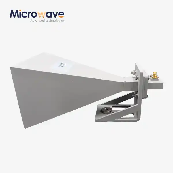 VIEW MOREWaveguide Horn Antennas
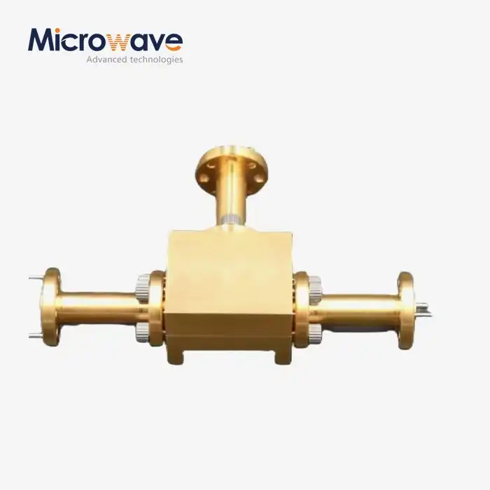 VIEW MOREWaveguide Power Divider
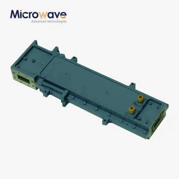 VIEW MOREHigh Power Waveguide Differential Phase Shift Circulator
 VIEW MOREWaveguide Single Channel Rotary Joint
 VIEW MORE90° Polarized Rotary Joint
 VIEW MOREWaveguide Short Plate
 VIEW MOREDouble Ridge Waveguide Load
 VIEW MOREDouble-Ridged Waveguide Broadwall Directional Coupler
