10, 20, or 30 dB? Picking the Right Coaxial Directional Coupler Value
Choosing the right coupling value for a coaxial directional coupler is one of those decisions that look straightforward on paper but carry real consequences in a live RF system. Whether you are monitoring forward power in a high-power transmitter, sampling a signal for automatic level control, or measuring reflected energy in a radar chain, the coupling value you select directly shapes how much signal reaches your detector, how much insertion loss your mainline absorbs, and how accurately your system reads what is happening. This guide breaks down the 10 dB, 20 dB, and 30 dB options with the technical depth that defense, satellite, and telecom procurement teams need to make a confident call.
Understanding Coaxial Directional Couplers and Coupling Values
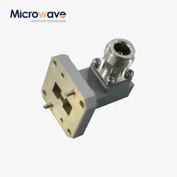
A coaxial directional coupler is a passive four-port device that sends a certain amount of electromagnetic power along a transmission line to a coupled port while largely leaving the mainline alone. A power divider divides power evenly, but a coaxial directional coupler can tell the difference between waves that are coming in and waves that are going back. Power dividers can't do this.
The coupling factor tells you how much linked port power there is compared to the input port power. It is given in decibels. A 10 dB coupler sends a tenth of the power coming in to the paired port. One-tenth is sent by a 20 dB coupler. One thousandth is what a 30 dB coupler gives you. Because of this logarithmic relationship, going from 10 dB to 30 dB greatly lowers the signal at the coupled port. This directly affects the sensitivity of the detector and the noise floor of the system.
A procurement engineer should check more than just the coupling factor. They should also check the directivity (ideally more than 30 dB for accurate measurements), VSWR (usually below 1.25:1 for low reflection), insertion loss on the through path (often less than 0.5 dB excluding coupling loss), and coupling flatness across the operating band (±0.5 dB for wideband applications). All of these factors together show whether or not a coupler will work properly across the L, S, C, X, and Ku bands in real-world situations.
Comparing 10 dB, 20 dB, and 30 dB Couplers for Different Applications
It's not a guessing game to find the right connection number for the job. Each number has its own performance range, and picking the wrong one can hurt the accuracy of measurements and the efficiency of the system. A coaxial directional coupler selection should be based on real-world requirements.
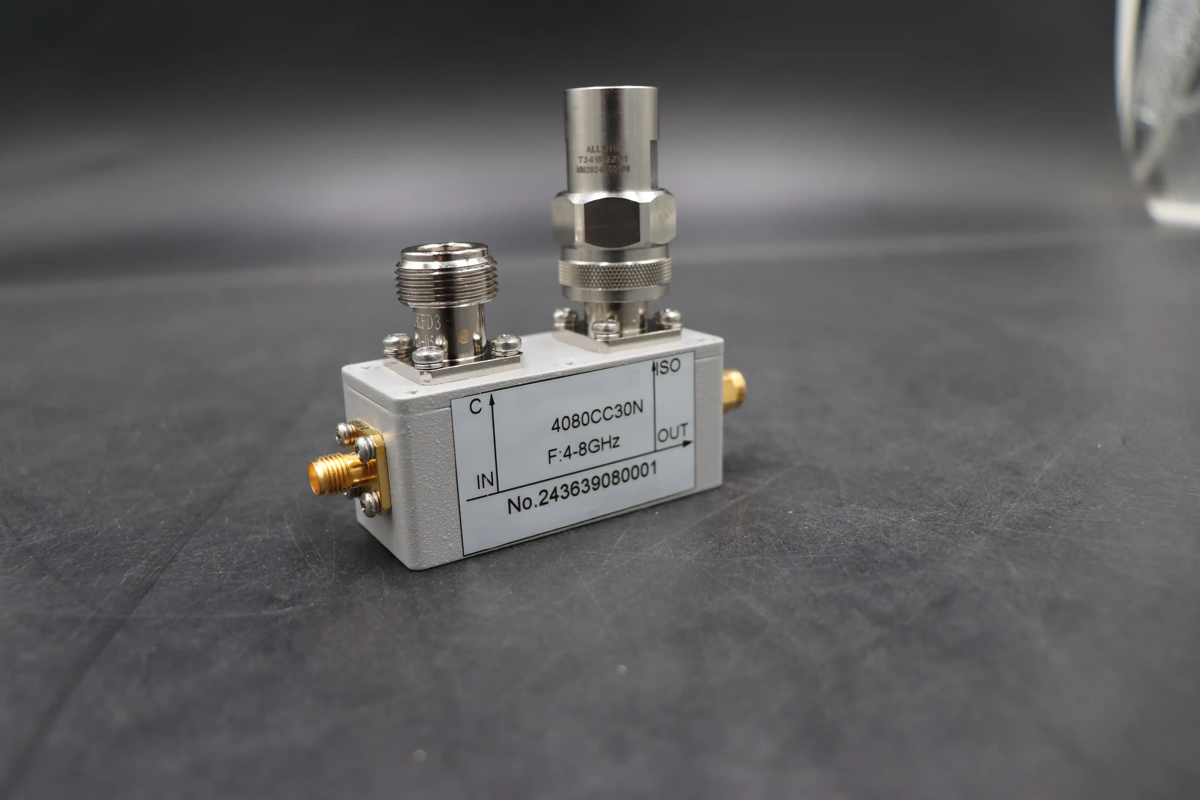
Here is how the three standard values map to real-world scenarios:
- 10 dB coupling transfers about 10% of the stream power to the coupled port. This value works well for high-power monitoring situations like radar transmitter chains and high-power amplifier test benches, where the detector or power sensor needs a strong signal level to give a correct reading. Higher coupling values come at the cost of a little more central entry loss.
- 20 dB coupling strikes a good compromise between signal access and mainline clarity. It is the most common way to test RF in general, check automatic level control loops in communication transmitters, and keep an eye on distributed antenna systems. At 20 dB, the coupled signal is strong enough for most detector systems, and it doesn't affect the stream much.
- 30 dB coupling extracts only 0.1% of the mainline power. This number is best used in sensitive measurement settings like Vector Network Analyzer (VNA) extension setups, laboratory reflectometer configurations, and electronic warfare receiver chains, where keeping the core signal intact is the most important thing. Since the coupled output isn't very strong, detector sensitivity becomes an issue at the system level.
These differences have real-world effects. In a high-power broadcast chain, a 30 dB coupler could leave the detector without enough power. In a precision measurement setting, a 10 dB coupler could add extra load that isn't needed. It's also important that the coupling is flat. For example, wideband aerospace and EW applications need flatness within ±0.5 dB across multi-octave spans, while narrowband telecom links can handle a little more variation.
Technical Insights: Design Principles and Performance Trade-Offs
Construction Techniques Behind Coupling Values
What controls how much energy moves from the trunk to the coupled line is the physical shape of the coupling structure. Lower dB values mean greater coupling. This can be achieved by making the spacing between the conductors closer or by making the coupling parts longer. When there is weaker coupling, the dB number is higher. To make stable, repeatable coupling across a wide frequency range, manufacturers use precision-machined aluminum or brass bodies that are filled with dielectrics and have stripline, air-line, and dielectric-filled coaxial structures. The bodies are often silver- or gold-plated.
Coaxial vs. Waveguide Couplers
Many ADM products cover frequencies from 0.5 GHz to 18 GHz and beyond with their coaxial directional coupler designs. They are also easy to add to system assemblies using N-type, SMA, or 2.92 mm connectors. Waveguide couplers can handle more power and lose less at millimeter-wave frequencies, but they have a smaller span and are bigger. Coaxial construction is still the most common way to build things for most satellite ground stations, military subsystems, and telecom equipment.
Insertion loss deserves particular attention. A 10 dB coupler is supposed to lose 10 dB from the trunk to the coupled port. However, the extra loss on the through path due to coupling leaks and conductor losses should stay below 0.5 dB. In cascaded RF chains, even a difference of 0.1 dB in extra loss adds up over many stages and lowers the overall noise figure of the system.
Procurement Considerations for B2B Clients: Buying the Right Coupler
Price, Lead Time, and Custom Orders
The most popular type of coaxial directional coupler is the standard 20 dB coupler in SMA format, which also has the shortest lead times. It takes longer and costs more to make custom coupling values, connector configurations that aren't standard, or housings that are toughened for aerospace qualification. Buyers with tight program plans should get clear on production and delivery windows right away, especially if they need high dependability or MIL-grade products.
Buying in bulk also gives you more power in negotiations. Locking in pricing deals with a seller that owns its production process, rather than a pure distributor, lowers exposure to spot-market price volatility for OEMs and contract makers that put together a lot of RF subsystems.
Connector Compatibility and Supplier Evaluation
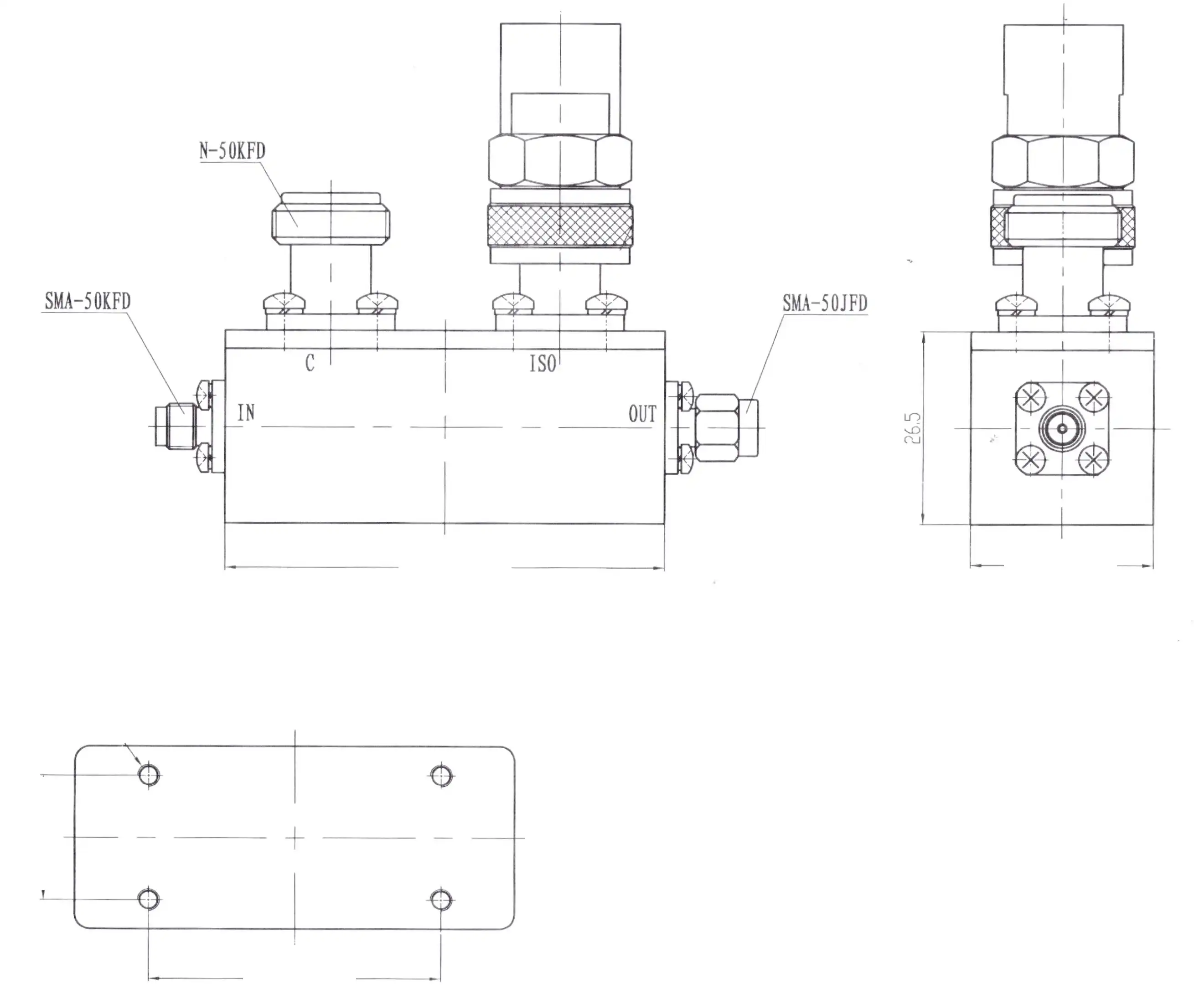
System interaction is directly affected by the type of connector. N-type connectors are common in many ground station and base station systems and can handle more power. SMA and 2.92 mm interfaces are most common in labs and small subsystems. Checking that the connectors will work together before buying them saves money on repairs.
When looking at suppliers, give more weight to companies that are ISO 9001 certified, have test data for each unit that is written down, and offer quick expert help. A seller that can offer OEM customization, quick turnaround on prototypes, and paperwork that can be tracked lowers procurement risk across all program stages.
Making the Final Choice: Best Practices and Recommendations
The right coaxial directional coupler value is found by carefully examining three factors: the signal level your detector needs, the amount of insertion loss your mainline budget can handle, and the directionality your measurement accuracy needs. For high-power broadcast tracking, 10 dB is the standard. Most of the time, 20 dB is a good default for telecom and ALC applications. 30 dB is the best level for keeping the mainline's purity in a precise lab or an EW receiver.
New developments in 5G mmWave technology and next-generation radar are driving the need for smaller, more direct radars with bigger bandwidth and lower PIM. As system architectures continue to improve, buyers who build partnerships with makers that can change specifications to meet new standards will stay ahead of the competition.
Conclusion
Choosing a coaxial directional coupler value is a technical choice that has effects on the procurement process. A 10 dB, 20 dB, or 30 dB value is used for different things in high-power monitoring, general RF systems, and precise measurement. When engineering and procurement teams understand insertion loss, directivity, VSWR, and coupling flatness, they can accurately match the requirements of a system to the specifications of a component. When you work with a manufacturer that has production know-how, strict quality standards, and the ability to customize, this choice at the component level becomes a reliable long-term asset.
FAQ
What does coupling factor mean in practical terms?
How much signal power is sent to the linked port is shown by the coupling factor. A 20 dB coupler sends only 1% of the power that comes in to the coupled port. The other 99% goes through the trunk. This has an effect on how big monitors and power sensors need to be in a tracking circuit.
Why does directivity matter so much for VSWR measurement?
How well the coupler separates forward and reflected signals is measured by its directivity. When there is low directivity, reflected energy can mess up the reading from the coupled port, which causes measurement error. It is strongly suggested that directivity be above 30 dB for accurate testing of return loss.
Can a directional coupler replace a power divider?
Not at all. With low separation between output ports, a power divider splits power in half. A coaxial directional coupler samples a small amount of power and has a high level of separation between directions. When you use a coupler as a combiner, you lose a lot of power and have trouble with separation. Each gadget does something different.
What connector type should I specify for high-power applications?
Because they have a strong mechanical interface and lower contact resistance, N-type connectors are the standard choice for high-power settings. When room is limited, SMA connections are best for small, low-power assemblies.
Partner with ADM for Precision Coaxial Directional Coupler Solutions
Every RF component that ADM makes is based on more than 20 years of experience making things. We are a reliable coaxial directional coupler supplier. Our products are ISO 9001-certified, and we can make OEM modifications, quickly turn around prototypes, and provide technical support for defense, satellite, and telecom uses. We will set up the right solution for you if you tell us the frequency range, coupling value, and power needs. You can email our tech team at craig@admicrowave.com to see all of our products.
References
1. Pozar, D. M. — Microwave Engineering, 4th Edition. Wiley, 2011.
2. Collin, R. E. — Foundations for Microwave Engineering, 2nd Edition. IEEE Press / Wiley-Interscience, 2001.
3. Matthaei, G., Young, L., & Jones, E. M. T. — Microwave Filters, Impedance-Matching Networks, and Coupling Structures. Artech House, 1980.
4. Mini-Circuits — Understanding Directional Couplers: Key Parameters and Application Notes. Mini-Circuits Technical Library, 2019.
5. Keysight Technologies — RF Component Fundamentals: Couplers, Splitters, and Combiners. Keysight Application Note 5991-2700EN, 2020.
6. IEEE Microwave Theory and Techniques Society — IEEE Transactions on Microwave Theory and Techniques, Vol. 68, No. 5. IEEE, 2020.