





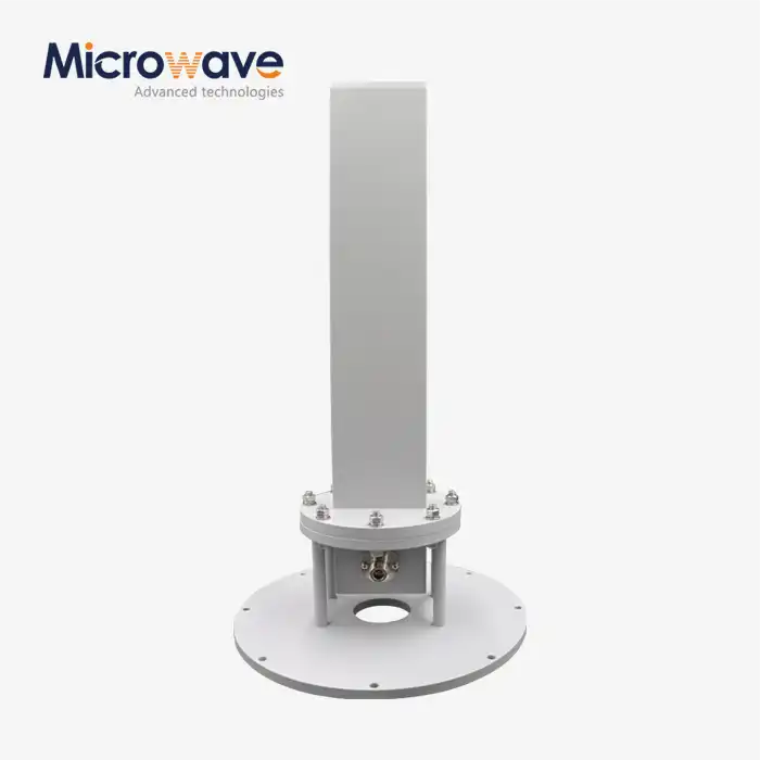
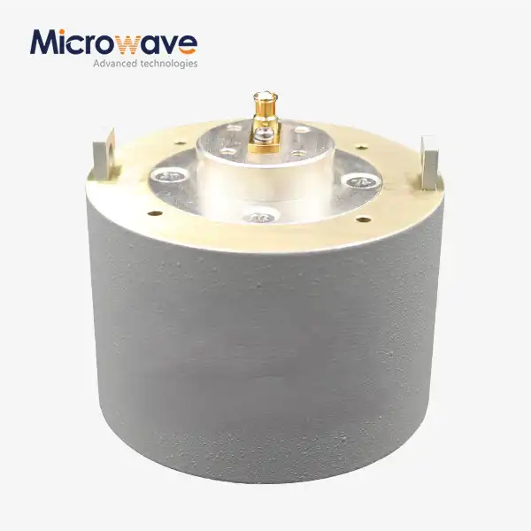
Antenna Near Field Measurement Probe
Antenna Near Field Measurement Probe for Planar, Cylindrical & Spherical Systems
Antenna Near Field Measurement Probes are made by Advanced Microwave Technologies Co., Ltd. (ADM) and can be used in time-domain, planar, cylindrical, and spherical near-field measurement systems. As a precise electromagnetic sensor, each probe measures amplitude and phase information in the near-field area of an Antenna Under Test (AUT), which is usually 3 to 10 wavelengths away from the aperture. For testing measurements, ADM has its own 24m Microwave Darkroom that can cover frequencies from 0.5 GHz to 110 GHz.
What Is an Antenna Near Field Measurement Probe?
The item is a special RF sensor that measures power and phase of a vector electromagnetic field in the near-field area of a device being tested (DUT).
Fourier Transform algorithms are used to re-create the far-field radiation pattern mathematically from the data that was collected. This gets rid of the need for big outdoor test ranges. Because of this, the probe is the most important part for testing satellite arrays, 5G Massive MIMO systems, and gain-sensitive antenna designs in small, soundproof rooms.
If the probe isn't very good, it can mess up the rebuilt pattern by adding unwanted reflections or not doing enough cross-polarization discrimination (XPD). To help with accurate probe correction during post-processing, ADM probes are marked with known gain and phase coefficients.
How the Probe Works in a Near-Field Measurement System
The probe moves across a clear opening, which can be flat, shaped like a cylinder, or circular, and takes vector field samples at each point. The near-field to far-field (NF-FF) transformation is based on this set of data.
Through probe correction (deconvolution), the probe's own radiation pattern is mathematically taken out during the transformation. If you don't do this step, the pattern of the probe will blur the AUT data and cause systematic measurement mistakes.
Each probe comes with a characterised adjustment file that has gain and phase coefficients for every frequency point. This lets the measurement software separate the probe's effect from the real performance of the DUT.


Probe Types and Application Scenarios
ADM supplies probes suited to different measurement priorities:
Probe Type | Key Characteristics | Typical Application |
Open-Ended Waveguide (OEWG) | Highest polarization purity, predictable pattern symmetry, stable gain reference | High-precision near-field scans, gain-critical measurements |
Dual-Polarized Probe | Captures two orthogonal polarizations in a single scan pass | Applications where scan time is a constraint |
Dual-Ridged Horn | Wideband coverage (e.g., 6–18 GHz or 18–40 GHz) | Broadband surveys where wideband coverage is the primary requirement |
Log-Periodic Probe | Wide bandwidth | Limited use in NF systems due to phase center movement with frequency |
For millimeter-wave measurements at 60 GHz and above, mechanical alignment is especially critical for an Antenna Near Field Measurement Probe. A probe misalignment of 0.5 mm can introduce significant phase errors at these frequencies.
Key Technical Specifications
Parameter | Specification |
Frequency Range | 0.5 GHz – 110 GHz |
Measurement Type | Planar / Cylindrical / Spherical / Time-Domain Near-Field |
Field Data Captured | Amplitude and Phase (Vector) |
Scan Stand-Off Distance | Typically 3–10 wavelengths from AUT aperture |
Mechanical Axis / Electrical Boresight Alignment | Within 0.05 degrees |
Port-to-Port Isolation (Dual-Polarized) | > 30 dB |
CW Power Handling (Rigid Waveguide Probes) | Up to 100 W – 500 W (band dependent) |
Probe Correction File | Supplied with gain and phase coefficients |
Recalibration Interval | Every 2–3 years or after mechanical shock |
Quality Control and Calibration
Any mistake in the probe affects the measurement result of the DUT, so each probe is checked against a set error budget before it is sent out.
To make a full probe correction file, Full-Sphere Pattern Calibration maps the probe's gain and radiation pattern over an area that can be used for calibration. Orthogonality Verification makes sure that the probe's mechanical axis is within 0.05 degrees of being in line with its electrical boresight. This is a very important check for scan-plane accuracy.
Return Loss and Isolation Testing shows that dual-polarized probes have port-to-port isolation that is greater than 30 dB. For Phase Stability Testing, the wire is bent and heated over and over again to make sure that it works the same way during long scans.
Applications
ADM's near-field measurement probes are used across a range of RF testing scenarios:
· Satellite antenna characterization — large-aperture arrays tested in compact indoor chambers
· 5G / 6G antenna development — Massive MIMO systems requiring precise gain and beam characterization
· Aerospace and defense antenna testing — where outdoor far-field ranges are impractical
· Microwave component R&D — supporting engineers across the design, validation, and production phases
· Academic and laboratory measurement — institutions requiring traceable, characterized probes
ADM's Measurement Capability
ADM operates a 24m Microwave Darkroom equipped with an Antenna Plane Near and Far Field Measuring Recombination Chamber. This facility allows in-house validation of Antenna Near Field Measurement Probes across the full 0.5 GHz to 110 GHz operating range before delivery.
ADM's engineering team works across waveguide components, millimeter-wave antennas, coaxial assemblies, and satellite communication products, providing application context that supports accurate near-field measurement decisions. If you have specific requirements around frequency range, polarization configuration, or system compatibility, contact ADM to discuss your measurement setup.
FAQ
Q: When using a near-field measurement probe, why is it necessary to correct the probe?
A: Every probe sends out a different kind of energy. Probe correction is a deconvolution process that takes out the known pattern of the probe from the measured data. This shows only the DUT's real performance. This step can be done easily and correctly with probes that come with known correction coefficients.
Q: Which probe should I get? An OEWG or a dual-polarized probe?
A: OEWG probes are the best for precise readings because they offer the purest polarisation and a stable gain reference. Dual-polarized probes pick up both polarisations in a single scan pass, which speeds up the gathering process when speed is important.
Q: How often should the calibration of a near-field measurement probe be done?
A: In normal use, the industry suggests recertification every two to three years. It should also be done right away if the probe is dropped or mechanically shocked. Changes in the aperture's shape have a direct effect on the accuracy of the gain and phase center.
Q: What's the difference between a Log-Periodic probe and an OEWG probe?
A: OEWG probes are the best for near-field scanning because they have more pure polarisation and a stable phase center that you can count on. Log-Periodic antennas cover more frequency ranges, but the phase center moves with frequency, which makes the probe correction calculation more difficult.
Q: How does the stand-off distance change the results of a measurement?
A: If you put the probe too close to the DUT—within a few wavelengths—it enters the reactive near-field zone. This is where inductive coupling can change the impedance of the DUT. To stay in the radiating near-field region, measurements should be taken at a certain stand-off distance.
Q: How much power can near-field measurement tools handle?
A: These probes mostly work as passive devices that receive signals. Most rigid waveguide probes can handle CW power of up to 100 W to 500 W, but this depends on the frequency band. In real life, the coaxial-to-waveguide adapter is often the part that can't handle as much power.
Contact Us
Have questions about selecting the right Antenna Near Field Measurement Probe? Reach our engineering team at craig@admicrowave.com — we're ready to assist.
YOU MAY LIKE
 VIEW MOREMMDS Transmitting Antenna
 VIEW MOREConical Horn Lens Antenna
 VIEW MOREFeed Fired Lens Antenna
 VIEW MOREMini Wideband Double-ridged Horn Antenna
 VIEW MOREConical Dual circular Polarization Horn Antenna
 VIEW MOREConical Linear Polarization Horn Antenna
 VIEW MORELow Side Lobe Diagonal Linear Polarization Horn Antenna
 VIEW MOREPlanar Spiral Antenna
