Why Coupling Hole Arrays Define Broadwall Coupler Directivity?
Coupling hole arrays are the defining physical feature that determines directivity in a broadwall directional coupler. Directivity — the ability to distinguish forward-traveling waves from reflected ones — depends entirely on the precise geometry of apertures machined into the shared broad wall between two rectangular waveguides. When hole size, spacing, and distribution follow an optimized pattern such as a Chebyshev or tapered design, the broadwall coupler achieves directivity exceeding 40 dB across the full waveguide band. Without that precision, forward and reverse wave separation degrades, making accurate power monitoring and VSWR measurement unreliable.
Understanding Directivity and the Physics Behind Coupling Hole Arrays
What Directivity Actually Means in Waveguide Systems
If the coupled power from a forward wave is less than or equal to the coupled power from a backward wave, this is called directivity. When the directivity figure is 40 dB, it means that the coupler blocks reflected signal interference 10,000 times better than before. This much space is needed to protect high-power tubes and keep signal measurement accurate in radar emitter chains and SATCOM transfer systems.
How Aperture Geometry Controls Electromagnetic Cancellation
Each hole in the array connects two different types of electromagnetic fields: the magnetic field and the electric field stray component. When put together, these two contributions move in opposite directions. When a wave moves forward, the two coupled signals add to each other in a good way at the coupled port. Both of them cancel out for a reverse wave. The accuracy of this cancelation, and therefore the directionality, relies on how far apart the holes are (usually in λg/4 steps) and how big each opening is. Directivity can drop by several decibels for every 2% change in opening width.
Why Array Distribution Patterns Matter
In narrow bands, uniform hole spacing gives good coupling flatness, but in the real world, systems need performance across full waveguide bands like X-band (8.2–12.4 GHz) or Ku-band (12.4–18 GHz). Chebyshev-weighted aperture arrays spread out the hole sizes based on Chebyshev polynomial coefficients. This makes the coupling flat across the whole band within ±0.5 dB to ±1.0 dB. A better roll-off is possible with tapered distributions. Both ways give defense and space acquisition teams the directivity stability they need.
From Single-Hole Designs to Precision Multi-Hole Arrays
The Limitation of Early Single-Aperture Couplers
In the beginning, waveguide broadwall couplers moved energy between guides through a single round hole. This method worked fine for measuring narrow bands in the lab, but it led to directivity values below 25 dB and coupling response changes of more than ±3 dB across even small bandwidths. Because of these problems, they couldn't be used for high-power radar tracking or SATCOM power amplifier linearization loops.
The Engineering Shift to Multi-Hole Configurations
Multi-hole arrangements turned out to be the answer. To get the desired wave cancelation, designers could use math instead of experience to spread the coupling across several apertures and change the size of each one. For example, a five-hole Chebyshev array has much better directivity than a single hole with the same total area. This is because the spatial interference pattern between linked signals works in a controlled, predictable way to both help and hurt.
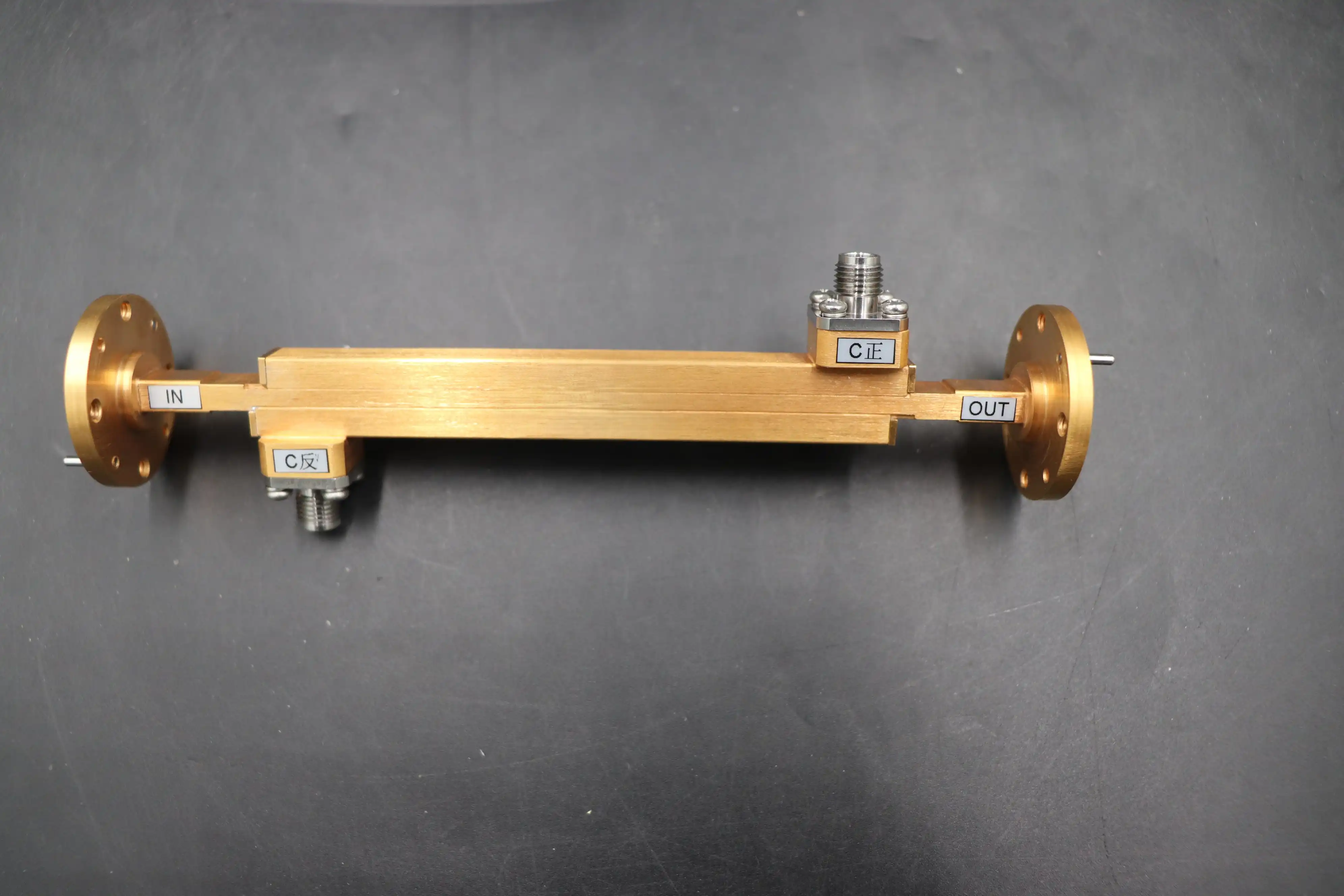
ADM's Manufacturing Approach to Aperture Precision
At ADM (Advanced Microwave Technologies Co., Ltd.), aperture arrays are machined to exact specifications that meet the directivity requirements. To lower ohmic losses and keep insertion loss below 0.1 dB on the main transmission line, parts are made from aluminum 6061, copper, or brass that has been plated with silver. A Vector Network Analyzer (VNA) is used to test all of the units over the entire working band. The S-parameter data includes coupling value (S31), main-line VSWR (S11), and directivity. ADM's goods are approved by ISO 9001:2015 and do not contain any harmful substances. They also meet the standards for traceability and paperwork that defense and satellite buying teams need.
Applications Where Hole Array Directivity Is Non-Negotiable
Precision directivity is not a specification choice; it is a practical condition. The following use cases show why.
When broadwall coupler directional couplers with precision hole arrays are used, these are the main situations:
- High-Power Military and Weather Radar: Couplers monitor output power from klystrons and traveling wave tubes (TWTs). High directivity allows engineers to detect VSWR spikes in the antenna feed and trigger protection circuits before tube damage occurs. These systems require designs that conform to MIL-DTL-85 environmental specifications.
- SATCOM Earth Station HPA Linearization: Deployed in high-power amplifier (HPA) pre-distortion loops at satellite ground stations, the coupler supplies a stable, direction-pure signal sample. Directivity errors translate directly into pre-distortion inaccuracies and degraded uplink linearity, a problem that worsens in outdoor installations with thermal cycling.
- Particle Accelerators and Industrial Microwave Heating: These systems demand continuous wave (CW) power handling at kilowatt levels. Coupler designs for these environments are often integrated with liquid cooling jackets, and aperture plating integrity must survive thermal expansion cycles verified through Environmental Stress Screening (ESS).
- Airborne Electronic Warfare Systems: In jamming suites covering 6–18 GHz, the coupler monitors output across multi-octave bands in high-vibration environments. Double-ridged waveguide variants extend bandwidth while maintaining directivity, making them suitable for airborne threat detection platforms.
One thing that all four of these uses have in common is that the signal sample that gets to the monitoring port can only show forward power and not a mix of forward and reflected energy. A well-designed lens array is the only way to be sure of this.
At these power levels, coaxial couplers can't match the insertion loss and directivity numbers that can be achieved with the right hole array design. The waveguide's air-dielectric design gets rid of the risk of dielectric breakdown, and the shape of the opening does the electromagnetic work that resistive or capacitive elements would do in lower-frequency coaxial options.
Procurement Evaluation: What B2B Buyers Should Request
VNA Test Data Across the Full Band
Ask for S-parameter sweeps instead of single-frequency summaries. It is necessary to check the directionality over the whole band that was given. In broadband radar ATE uses, a coupler that has 42 dB of directivity at the center frequency but only 28 dB at the band edges will not work. Every package from ADM comes with full VNA test documents.
Flange Interface and Aperture Dimensional Verification
The performance of both hermetic sealing and passive intermodulation (PIM) depends on how flat the flange is and how much room there is between the apertures. Buyers should make sure that the flanges meet the requirements for UG-cover or CPR and that the datasheet clearly states the aperture diameter tolerance. Dimensional non-conformance is one of the main reasons why directivity varies between production units.
Power Handling and Environmental Qualification
For versions with a lot of power, check the peak power rates under either dry nitrogen or SF6 pressure. Sourcing teams in aerospace should also ask for thermal cycling test results that show the aperture plating and internal termination loads stay stable over the full temperature range. These conditions can be met by ADM's goods, and you can contact their expert team at craig@admicrowave.com to look over their specifications.
Conclusion
This is not an accident that a broadwall coupler has coupling hole groups; they are what make the coupler useful for conducting electricity. How far apart, big, and spread out apertures are determines whether forward and backward waves are separated by 20 dB or 40 dB. This difference is what separates a working part from a protective part for a million-dollar transmission. If a procurement engineer knows about aperture physics, they can write better specifications, read datasheets more accurately, and avoid making substitutions that look the same on paper but don't work in real life.
FAQ
What directivity figure should I require for radar applications?
For radar power monitoring, require at least 40 dB directivity across the full operating band. This ensures that reflected wave contributions to the coupled port remain below 1% of the forward power sample, keeping power measurements accurate even when antenna VSWR fluctuates under dynamic load conditions.
How does aperture spacing affect bandwidth?
Aperture spacing set at λg/4 intervals at the center frequency gives good cancellation at that frequency. Chebyshev-weighted arrays adjust hole sizes so that cancellation remains effective across the entire band. Tighter bandwidth requirements allow uniform spacing; wider bandwidths require weighted distributions.
Can broadwall couplers handle continuous wave high-power loads?
Yes. Air-dielectric waveguide construction allows kilowatt- to megawatt-peak power handling. CW thermal loads require attention to plating integrity and, in industrial heating or accelerator applications, liquid cooling integration. ADM designs variants for both pulsed and CW environments.
What certifications should a supplier carry for defense procurement?
Look for ISO 9001:2015 quality management certification and RoHS compliance at minimum. Flange interfaces should meet MIL-DTL-85 or equivalent specifications. ADM holds ISO 9001:2015 and ISO 14001:2015 certifications, with full traceability documentation available for defense program requirements.
Source Your Next Broadwall Coupler from ADM
ADM is a reliable company that has been making broadwall couplers for over 20 years, helping defense, satellite, and research procurement teams around the world. We offer OEM customization of our waveguide parts to fit your exact frequency band, coupling value, and flange specifications. They are ISO 9001:2015 certified and have been fully VNA-tested. You can email our engineering team at craig@admicrowave.com to get detailed datasheets, samples, or a price quote for buying in bulk.
References
1. Pozar, D. M. Microwave Engineering, 4th ed. Wiley, 2011.
2. Montgomery, C. G., Dicke, R. H., and Purcell, E. M. Principles of Microwave Circuits. MIT Radiation Lab Series, McGraw-Hill, 1948.
3. Collin, R. E. Foundations for Microwave Engineering, 2nd ed. IEEE Press / Wiley-Interscience, 2001.
4. Levy, R. "Directional Couplers." Advances in Microwaves, Academic Press, 1966.
5. MIL-DTL-85 — Detail Specification: Connectors, Waveguide, Flanged, General Specification for. U.S. Department of Defense, 2003.
6. IEEE Standard 1785.1 — IEEE Standard for Rectangular Metallic Waveguides and Their Interfaces for Frequencies of 110 GHz and Above. IEEE, 2012.