





Gain Budget Analysis of Cassegrain Antennas in Deep-Space Links
When engineers design a deep-space communication link, every fraction of a decibel counts. Gain budget analysis sits at the center of that process, and cassegrain antennas have earned their place as the preferred aperture solution for ground stations and space-borne platforms alike. With aperture efficiencies reaching 65–70% and noise temperatures well below competing reflector types, the dual-reflector geometry delivers the signal margin that missions from low Earth orbit to the outer planets depend on. This article walks through the physics, the design trade-offs, real-world data, and procurement guidance you need to specify the right antenna.
Understanding Gain Budget in Deep-Space Links
What Gain Budget Actually Means
All the gains and losses along a one-way RF path are added up in the gain budget. These losses and gains include broadcast power, antenna gain, free-space path loss (FSPL), atmospheric absorption, direction error, and receiver noise figure. At 8–12 GHz in the X band, FSPL to Mars at opposition is already more than 270 dB. It only takes a 1 dB drop in the gain budget for the data rate to drop from kilobits to bits per second.
Key Variables Engineers Track
Every deep-space link budget is based on three things: antenna gain (dBi), system noise temperature (Tsys in Kelvin), and the figure of merit G/T (dB/K). The G/T values of NASA's Deep Space Network 34 m beam-waveguide dishes are very close to 49 dB/K at X-band, and these dishes are often used as an example by commercial and defense procurement teams.
Why SNR Margin Is Non-Negotiable
The signal-to-noise ratio margin must stay positive throughout the entire mission arc, from launch to planetary encounter. A standard rule for design is to leave a margin of at least 3 decibels. Atmospheric water vapor absorption peaks at 22 GHz and 60 GHz, so the choice of frequency and antenna gain directly affects whether a link stays alive during rain-fade or solar-conjunction events. You have to do a precise gain budget estimate; it's the design gate that comes before buying any gear.
Design Principles of Cassegrain Antennas Affecting Gain
The Dual-Reflector Advantage
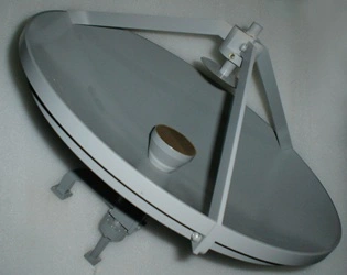
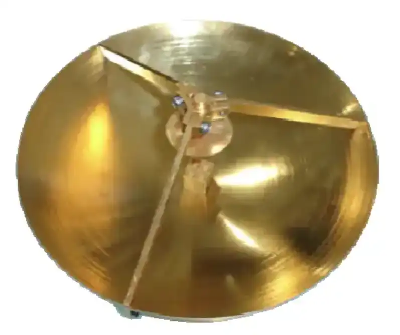
You can find a big parabolic primary and a convex hyperbolic sub-reflector in a traditional Cassegrain antenna. This setup makes the effective focal length (EFL) two to four times longer than the actual back-focal distance. This longer EFL lowers phase-center sensitivity and lets the feed horn light up the sub-reflector at a wider subtended angle. This directly raises the on-axis gain and aperture efficiency.
Feed Horn Selection and Its Impact
There is a standard way to work in deep space with scalar corrugated feed horns. These horns have low-sidelobe patterns that keep spillover loss below 0.3 dB at the sub-reflector edge. Potter horns with two modes are a smaller option with narrower bandwidths. ADM makes and tests feed horns to make sure they meet the requirements of ITU-R S.580 for sidelobe envelope compliance. They also make sure that the surface RMS accuracy is better than »/20 at the target frequency, which is shown by laser tracker reports during final acceptance testing.
Thermal Stability Across Operational Ranges
Carbon-fiber-reinforced polymer (CFRP) reflector panels keep their surface accuracy within 0.2 mm RMS even when the temperature changes from -40 °C to +60 °C, which is a normal range for ground stations that are left open to the elements. Stretch-formed aluminum plates are a cheaper option for job cycles that aren't as demanding. In either case, keeping the surface accurate across temperature keeps the loss of gain below 0.5 dB, which is a key budget item for tasks that last a long time.
Comparative Analysis: Cassegrain Antennas vs. Alternatives in Gain Budget
Picking the right reflector design affects more than just peak gain. It also impacts sidelobe performance, bandwidth, and the device's ability to last for a long time. These are the main trade-offs that come up with the most popular reflector designs:
- Offset-fed parabolic reflector: Eliminates sub-reflector blockage entirely, which improves gain by roughly 0.5–1.0 dB on small apertures (under 50λ). However, cross-polarization discrimination (XPD) degrades unless a corrective feed network is added, and mounting the feed on an asymmetric arm introduces structural asymmetry that complicates large-dish fabrication.
- Gregorian Cassegrain: Replaces the hyperbolic sub-reflector with a concave ellipsoidal one located beyond the primary focus. Spillover is easier to shield with a shroud, which lowers sky-noise contribution. The trade-off is a physically longer system and higher structural mass — acceptable for fixed ground stations but prohibitive for spacecraft.
- Helical antenna: Simple to build and naturally circularly polarized, but aperture efficiency rarely exceeds 50%, and gain scales poorly beyond 20 dBi. It suits CubeSat uplinks but cannot compete with a 3 m dish in a deep-space scenario.
- Prime-focus parabolic: The feed is suspended at the focal point, creating blockage and long waveguide runs. At Ka-band (26.5–40 GHz), every additional 30 cm of waveguide costs roughly 0.4 dB. The Cassegrain architecture moves active electronics to the hub, removing that loss entirely.
When teams that buy things compare bids, these differences matter. At Ka-band, a Cassegrain antenna design usually has 2–4 dB better G/T than a prime-focus dish of the same size. This means that higher data rates are possible or the aperture can be smaller and cheaper.
Case Studies: Gain Budget Applications in Real-World Deep-Space Links
Case Study 1 — Satellite Ground Station Upgrade
A telecom company changed a Ku/Ka gateway from 4.5 m prime-focus geometry to 4.5 m Cassegrain antenna geometry and noted a 3.1 dB/K improvement in G/T after changing the front-mounted LNA chain with a hub-mounted low-noise block. The calculated gain budget improvement was mostly due to getting rid of 1.8 m of elliptical waveguide (which lost about 1.4 dB) and cutting down on feed spillover by 0.7 dB. The rain-fade margin went up from 2.8 dB to 5.9 dB, which met the operator's new goal of 99.9% annual uptime.
Case Study 2 — Deep-Space Probe Telemetry Reception
A college research group that wanted to get data from an interplanetary CubeSat at 8.4 GHz used a 2.4-meter prime-focus dish with a G/T of 18.2 dB/K at first. When we switched to a 2.4 m Cassegrain system with an 8% sub-reflector blocking ratio, G/T went up to 21.5 dB/K, which is a gain of 3.3 dB/K. At a 0.8 AU link distance, that cushion brought back a 4 kbps data rate from a link that couldn't be used before during times of solar conjunction. The lesson is that changes in shape alone, without making the opening bigger, can save a link budget that is on the edge.
Procurement Considerations for High-Performance Cassegrain Antennas
Matching Specifications to Mission Requirements
Do not start with the catalog, but with the link budget. Needed G/T, frequency band, polarization (linear, circular, or dual), and pointing method (fixed, az-el, or 3-axis) all affect the width of the reflector, the accuracy class of the surface, and the complexity of the feed network. If you match any of these to a cheaper version, you'll probably end up with more system-level work to do than you save.
Evaluating Suppliers and Quality Documentation
Suppliers of reliable cassegrain antennas give factory acceptance test (FAT) data that includes measured gain, VSWR (usually ≤1.3:1), and sidelobe pattern plots against regulatory masks. For outdoor uses, it is normal to test for salt spray according to ASTM B117 and give rates for wind speeds up to 200 km/h. Production and research and development (R&D) at ADM happen in the same building. All of their goods are certified with ISO 9001:2015 and have full material traceability, which is information that defense and aerospace procurement teams need when they give a contract.
Total Cost of Ownership
When electronics are hub-mounted in a cassegrain system, the mean time to repair (MTTR) is shorter because techs can reach amps and feed networks from the back of the dish without having to stand on high work platforms. Over the life of a 15-year ground station, this difference in maintenance access can make up for a higher initial unit cost. ADM offers bulk purchase deals and OEM documentation packages for system integrators who need to use the same part specs in more than one installation.
Conclusion
A study of the gain budget makes it clear why cassegrain antennas are still the best shape for links in deep space. At the same aperture size, the dual-reflector design has better sidelobe patterns, lower system noise temperature, and higher aperture efficiency than most other options. A verified link budget matched to a seller who can provide full FAT paperwork and long-term support is the best place for procurement engineers at defense companies, satellite integrators, or research institutions to start. ADM has been making precise RF and microwave parts for more than 20 years, and our team is ready to help you with your next project from the specifications to the delivery.
FAQ
Why does a cassegrain antenna have better G/T than a prime-focus dish of the same diameter?
The feed horn points toward the cold sky via the sub-reflector rather than toward the warm ground, which lowers the antenna noise temperature by 10–20 K. Combined with eliminating long waveguide runs, the net G/T improvement at Ka-band routinely reaches 2–4 dB/K.
What sub-reflector blockage ratio is acceptable for deep-space work?
Blockage ratios below 10% of the main aperture area have negligible effect on gain for dishes larger than 2 m at X-band. Standing-wave issues between the feed and sub-reflector are managed with a vertex matching plate or geometric shaping on the sub-reflector surface.
Can an existing prime-focus dish be retrofitted to cassegrain geometry?
Generally not. Prime-focus dishes carry an f/D ratio of 0.3–0.4. Cassegrain systems require an f/D of 0.6–0.8 on the primary reflector to accommodate the sub-reflector optics correctly. A full reflector replacement is typically necessary.
What surface accuracy is required at Ka-band?
Surface RMS error should remain within λ/20, which equates to roughly 0.25 mm at 32 GHz. CFRP panels verified by photogrammetry or laser tracker routinely achieve 0.15–0.20 mm RMS.
Partner With ADM for Your Next Cassegrain Antenna Project
Defense OEMs, satellite integrators, and research institutions in the US and around the world buy precision Cassegrain antennas and full RF assemblies from ADM. ADM has been making Cassegrain antennas for a long time and backs up every product with ISO 9001:2015 paperwork, full FAT data, and dedicated engineering support. To get a unique specification review and price, please email our team at craig@admicrowave.com.
References
1. Ruze, J. — "Antenna Tolerance Theory — A Review." Proceedings of the IEEE, 1966.
2. Imbriale, W. A. — Large Antennas of the Deep Space Network. Jet Propulsion Laboratory / Wiley-Interscience, 2003.
3. Pratt, T., Bostian, C., & Allnutt, J. — Satellite Communications, 2nd ed. Wiley, 2003.
4. Stutzman, W. L., & Thiele, G. A. — Antenna Theory and Design, 3rd ed. Wiley, 2012.
5. ITU-R Recommendation S.580-6 — "Radiation Diagrams for Use as Design Objectives for Antennas of Earth Stations Operating with Geostationary Satellites." International Telecommunication Union, 2004.
6. Goldsmith, P. F. — Quasioptical Systems: Gaussian Beam Quasioptical Propagation and Applications. IEEE Press / Wiley, 1998.
YOU MAY LIKE
 VIEW MORESlotted Waveguide Array Antenna
 VIEW MORELow Ku Band Diplexer
 VIEW MOREWaveguide Miter Bend
 VIEW MOREFlexible Twistable Waveguide
 VIEW MOREHigh Power Waveguide Differential Phase Shift Isolator
 VIEW MOREDouble Ridge Waveguide Tube
 VIEW MORECoaxial Fixed Attenuator
 VIEW MOREHigh Power Coaxial Switch
