Waveguide Anti-leak Gasket
Waveguide Anti-leak Gasket for RF & Microwave Systems
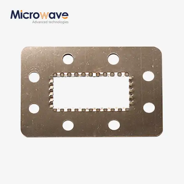
Advanced Microwave Technologies Co., Ltd. (ADM) makes Waveguide Anti-leak Gaskets for RF and microwave communication systems that need to keep the signal integrity and the environment sealed. Electrical energy can't get out of the flange joints because of these gaskets. They also keep moisture, dust, and outside interference from getting into the waveguide cavity. Its volume resistivity is less than 0.010 ohm-cm, its shielding effectiveness is more than 100 dB at 10 GHz, and its Shore A hardness is between 65 and 85. It can work in temperatures ranging from -55°C to +160°C.
What Is a Waveguide Anti-leak Gasket?
Putting a product at the point where waveguide assemblies meet flanges is a good idea because it helps seal the joint. One thing it does is stop EMI leaks to protect the security of the signal. Another thing it does is seal out moisture, dust, and changes in pressure.
Most O-rings aren't made to work this way. They aren't good enough at moving electricity to keep low-impedance continuity across flange joints like WR-90 or WR-137. The small holes between metal flanges can act like slot antennas if they aren't properly sealed. They can send energy outward and cause insertion loss, which is also known as joint discontinuity.
You can also use dry air or nitrogen to blow up the seal from the inside. In high-power systems, having water inside the waveguide can lead to voltage breakdown (arcing), so it's not just a safety measure to keep the inside atmosphere dry.
Material Composition
The performance of each anti-leak gasket depends on its material selection. ADM uses silicone or fluorosilicone elastomers loaded with conductive particles matched to the flange material and operating environment.
Conductive Filler | Best Paired With | Key Benefit |
Silver-Plated Aluminum (Ag/Al) | Aluminum flanges | Keeps electrochemical potential difference below 0.25V, reducing galvanic corrosion risk |
Silver-Plated Copper (Ag/Cu) | Copper and brass flanges | High conductivity with stable contact resistance |
Nickel-Graphite | General-purpose applications | Cost-effective option with reliable shielding performance |
Selecting the wrong filler for a given flange material can cause corrosion at the interface over time, degrading both the environmental seal and the electrical continuity path.
Key Technical Parameters
Parameter | Value / Range |
Base Elastomer | Silicone / Fluorosilicone |
Conductive Filler Options | Ag/Al, Ag/Cu, Nickel-Graphite |
Shore A Hardness | 65 – 85 |
Operating Temperature | -55°C to +160°C |
Volume Resistivity | < 0.010 ohm-cm |
Shielding Effectiveness | > 100 dB at 10 GHz (plane wave) |
Environmental Sealing Level | IP67 / IP68 |
Dimensional Tolerance | ±0.005 inches |
Compatible Flange Styles | CPR, CMR, UG, WR-series |
Application Scenarios
Marine Radar and Naval Defense Systems
X-band radar equipment on ships are constantly exposed to salt fog. For accurate radar signal processing, the gasket must keep out saltwater, which can cause arcing right away, while still letting electricity flow. The IP67/IP68 rating for sealing is important here, as is the fact that the gasket filler must be able to work with aluminium or steel flanges that are popular in marine enclosures.
Satellite Communication Earth Stations
High-power amplifiers (HPA) that are outside are exposed to UV light and the temperature changes a lot from day to nite. The gasket keeps dry air or nitrogen under pressure inside the waveguide. This keeps condensation from forming on the walls of the waveguide when the temperature changes.
5G and Millimeter-Wave Microwave Backhaul Links
Tower-mounted equipment has to keep its RF sealing integrity even when it rains or gets very cold. At millimeter-wave frequencies, even small changes in impedance at flange joints can have measurable effects on insertion loss and VSWR. This is why the consistency of the gasket's dimensions and its ability to conduct electricity are important selection criteria.
Airborne and Aerospace Systems
The operating range of -55°C to +160°C includes normal thermal cycling profiles in aircraft. As shown by ASTM D471 immersion testing, fluorosilicone gaskets work best in these conditions because they can handle being exposed to fuel and hydraulic fluid.
Electronic Countermeasures (ECM) and Radar
Signal leaks at waveguide joints can hurt phase coherence and cause unwanted emissions that mess up channels next to them in ECM and active radar systems. At the joint level, the Waveguide Anti-leak Gasket stops these effects by making a continuous low-impedance flange contact.
Quality Control and Testing
ADM uses written inspection procedures to make sure that gaskets work properly before they are shipped.
Visual and Dimensional Checks
To make sure that each gasket fits standard flange configurations, it is checked against a range of ±0.005 inches. Every part is checked for moulding flash; too much flash at the flange seating surface can stop the continuation of RF grounding at the joint.
Volume Resistivity Testing per MIL-DTL-83528
This test checks the conductivity at a certain crushing pressure. It proves that the gasket creates an electrical path with low resistance across the flange joint, which is in line with the requirement of less than 0.010 ohm-cm.
Compression Deflection and Set Testing per ASTM D395
This test proves that the gasket springs back after being compressed by flange torque for a long time. If a gasket doesn't bounce, it can't fill in surface holes in the flange face. This lets RF leak through over the assembly's service life.
Fluid Immersion Testing per ASTM D471
Jet fuel, hydraulic fluids, and de-icing solvents are used to test gaskets for use in aerospace applications to make sure they are resistant. This proves that the seal stays intact in chemical environments that are common on bases in the air.
Installation and Handling
Correct installation has a direct effect on how well the gasket works in service.
When tightening flange bolts, use a torque sequence with a star shape. When you tighten the bolts around the edge one at a time, the gasket is unevenly compressed. One side is over-compressed while the other side stays under-compressed, which creates RF gaps.
Do not over-compress. If the gasket sticks out into the waveguide opening, it makes a spot of low impedance that makes VSWR and insertion loss worse. When installed correctly, the gasket should fit snugly inside the groove in the flange and stay out of the way of the radio waves.
After removing gaskets, do not use them again.The elastomer in a gasket stops being able to rebound to smooth out flange surface imperfections after it has been compressed during its service cycle or after being exposed to repeated thermal cycling. Putting a used gasket back in place raises the chance of RF leaking at the joint.
Customization Options
ADM can make custom Waveguide Anti-leak Gaskets for flange configurations that aren't common. Based on what your system needs, you can choose the elastomer base, the type of conductive filler, the gasket geometry, and the dimensional tolerances.
For High Power Microwave (HPM) uses, deep gasket channels or conductive die-cut gaskets can be provided to move the gasket out of the way of the E-field peak. This lowers the chance of multipaction or ionisation breakdown at the joint interface.
When you call ADM's engineering team to ask for a custom configuration, you must include your flange drawing and the frequency range you want to use.
FAQ
Q: What can be done to stop galvanic corrosion between the gasket and the flange?
A: To begin, match the conductive filler to the base material of the flange. Electricity levels stay below 0.25V when Silver-Plated Aluminium (Ag/Al) filled seals are used on aluminium flanges. Putting an Ag/Cu filler against an aluminium flange, for example, raises the potential difference and speeds up corrosion at the contact interface.
Q: Can these gaskets be used again after taking something apart for maintenance?
A: It's not a good idea to reuse. The elastomer loses its ability to fully rebound after being compressed and heated and cooled many times in service. If you replace the gasket in this state, it might not fully cover the flange surface, which raises the risk of RF leakage.
Q: Will the gasket change the VSWR of the system?
A: VSWR shouldn't be affected by a gasket that is installed correctly. A localised impedance discontinuity is made when gasket material is forced into the waveguide aperture by over-compression. This won't happen if you stay in the recommended compression range and use a star-pattern torque sequence.
Q: What's the difference between base materials made of silicone and fluorosilicone?
A: Silicone works from -55°C to +160°C and is good for most ground-based and satellite uses. Fluorosilicone is better at protecting against fuel, hydraulic fluid, and solvents, which is useful for aircraft and naval installations where chemicals are likely to come into touch.
Contact Us
Send your flange drawing, frequency range, or application details for the Waveguide Anti-leak Gasket to craig@admicrowave.com. ADM's engineering team will review your requirements and follow up directly.