How Do You Match a High Power Waveguide Isolator to Your PA Output?
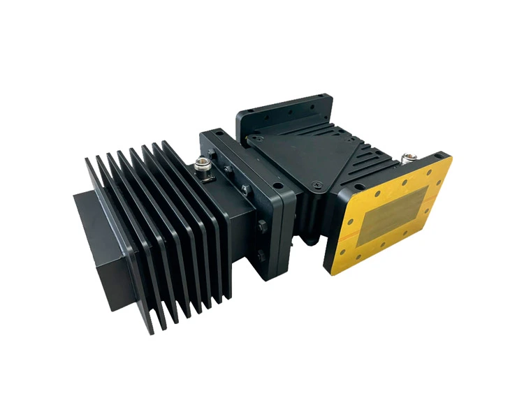
Matching a high power waveguide isolator to your power amplifier (PA) output comes down to aligning five parameters: forward power rating, operating frequency band, insertion loss, isolation level, and flange interface. Your isolator must handle the PA's maximum output — ADM's standard units support up to 1000 W forward power — while covering the full signal bandwidth (typically 800 MHz) with insertion loss no greater than 0.3 dB. Getting this match right prevents reflected energy from damaging your amplifier stage and keeps the entire RF chain stable under load.
Understanding the Role of Waveguide Isolators in PA Systems
For each part, it's helpful to know what it does in the transmitter chain before choosing it. This part breaks down how it works, what the important electrical parameters are, and why mismatches have real effects.
How Ferrite-Based Isolation Works
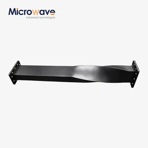
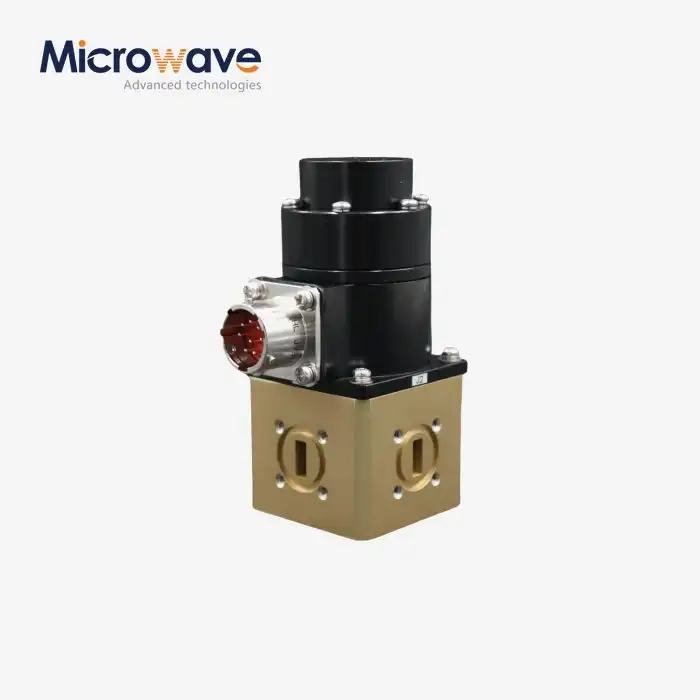
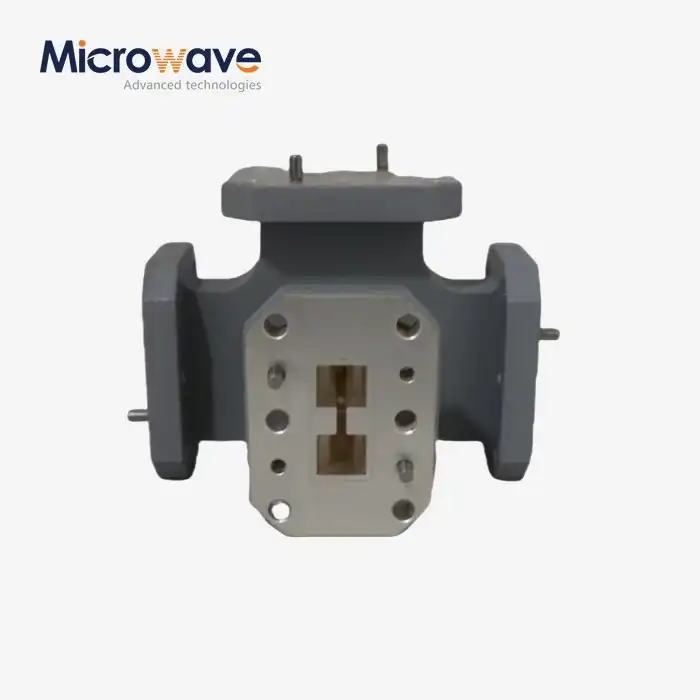
A waveguide isolator is a passive device with two ports that doesn't work both ways. A ferrite slab is inside the rectangular waveguide housing and is surrounded by a permanent magnet field that pulls it in one direction. Forward-traveling RF energy goes through with almost no loss. The ferrite-loaded termination takes in reverse-traveling energy that is reflected from antenna mismatches or changes in the load. VSWR spikes can't damage sensitive sources like solid-state power amplifiers (SSPAs) and traveling wave tubes (TWTs) because of the way they behave in a certain direction.
Key Electrical Parameters to Know
Insertion loss, isolation ratio, VSWR, and bandwidth are the things that show how well an isolator works in a PA chain. The waveguide isolators from ADM have an 800 MHz operating bandwidth, 20 dB of typical isolation, and 0.3 dB of typical insertion loss. Even 0.2 dB of insertion loss creates about 450 W of internal heat at 10 kW input. This is why thermal management is not a choice but an engineering must.
Why Proper Matching Extends PA Lifespan
If the isolator is too small for the output stage of your PA, it will overheat when reverse power is applied for a long time. This makes the ferrite material get closer to its Curie temperature, which breaks down the magnetic bias and makes the separation less effective. Researchers writing in IEEE Transactions on Microwave Theory and Techniques have found that isolator power rates are often to blame for amplifier failures in radar emitters.

Key Criteria for Matching Isolators to PA Outputs
It takes more than checking a box on a paper to choose the right component. Here are the main things your tech team should think about before making a decision about what to buy.
Power Handling: Average vs. Peak
High power waveguide isolator values cover two separate ranges. Thermal stability, or how much heat the ferrite assembly can keep off, is based on average power. The voltage level that must be reached before arcing happens inside the waveguide is set by the peak power. The units from ADM can handle up to 1000 W of forward power, and their Al/Cu construction makes them good at moving heat. To keep a safe thermal margin, always lower the forward power to 80% of its rating value when the operation is constant.
Frequency Band Compatibility
For the PA to work, your isolator must completely block out the sound. When there is a mismatch at the band ends, insertion loss spikes happen, which lowers the efficiency of the emitter and raises VSWR. ADM has isolators for the L, S, C, X, Ku, and Ka bands. Each isolator is designed to work best with the waveguide measurements of a different frequency range. Look at the S21 response curve in the datasheet to make sure that the frequency you need is in the flat part of the device's passband and not at its edges.
Flange Type and Mechanical Interface
Make sure that the mechanical link between your PA output and the isolator input is correct. Standard flange choices include UG, CPR, and unique shapes and sizes. Isolators from ADM can be made in any size and flange shape to perfectly fit OEM installs. Check the working temperature range as well as the flange shape. ADM's units can handle temperatures between -40 °C and +70 °C, which is enough for most industrial and outdoor telecom applications.
Comparing Waveguide Isolators with Alternative RF Protection Solutions
RF engineers sometimes wonder if a circulator or a coaxial ferrite isolator can protect in the same way. The answer is different for each system based on its power level, frequency, and design.
Waveguide Isolators vs. Circulators
An isolator is basically a circulator with port 3 terminated in a matched high-power load. A circulator has three ports. Because it doesn't handle load from outside, the isolator is the best choice when you need a simple two-port drop-in replacement at the PA output. When reflected power needs to be sent to a separate path for monitoring or dumping, circulators make more sense. In high-power waveguide systems, isolators are usually used to protect the PA.
Waveguide vs. Coaxial Ferrite Isolators
Coaxial ferrite isolators work well at lower power levels, usually less than 100 W. When that level is reached, the center wire and dielectric in coaxial systems start to lose heat. With waveguide isolators, this problem is completely solved because there is no center line and power is spread out across the waveguide cross-section. Isolators in waveguide format are used in all kilowatt-class transmitter chains in radar, satellite uplinks, and military systems because of this change in structure.
Low Loss vs. High Isolation Trade-Off
The level of load mismatch determines whether you should use a normal 20 dB isolation unit or a higher-isolation cascaded design. A single-stage 20 dB high power waveguide isolator is enough when the receiver VSWR is less than 2.0:1. For bigger mismatches, like those that happen in industrial microwave heating or plasma production, you need stages that are stacked on top of each other and offer 40–60 dB of separation. As a result, each stage adds about 0.3 dB of insertion loss, which you need to plan for in your link margin.
Practical Steps to Test and Verify Your Isolator Match
Once you've chosen a possible isolator, proof testing makes sure that the part works the way it's supposed to in your real system.
Vector Network Analyzer (VNA) Characterization
Connect the isolator to a VNA that has been adjusted and measure S21 (insertion loss), S12 (isolation), and S11/S22 (return loss) over the whole working band. Across the whole band, the S12 value should stay at or below -20 dB. Any rolloff toward the band edges means that the waveguide dimensions don't match up with the operating range of the ferrite material. To make sure the temperature is stable, run this check from -40 °C to +70 °C, which is the working temperature range.
High-Power Burn-In and Aging Test
After the VNA is checked, the isolator must be put through a full-power age test for at least four hours at its full rated forward power. Use a thermal camera to keep an eye on the temperature of the case. The ferrite assembly should reach thermal balance without going over the highest temperature that the material can handle. Because ADM is made of Al and Cu, it has the right thermal conductivity to pass this test regularly across production runs.
Real-World Case: Matching an Isolator for a 10 GHz PA
An X-band radar PA that puts out 500 W and has a moving antenna load (VSWR varies between 1.5:1 and 2.5:1) needs an isolator that can handle at least 625 W of average forward power (80% derating) and at least 20 dB of isolation. With a 1000 W forward power ceiling and 0.3 dB insertion loss, ADM's X-band waveguide isolator gives you the headroom you need. The VNA test showed that S12 was less than -22 dB across the whole X-band range in this setup.
Procuring the Right Waveguide Isolator for Your System
The last step is to find a provider whose quality standards, paperwork, and ability to help you make changes meet your needs.

What to Look for in a Manufacturer
Give more weight to suppliers who are ISO 9001 certified, have passed environmental tests like thermal cycling and vibrations according to MIL-STD-810 or an equivalent standard, and send full S-parameter datasheets with every unit. ADM is certified to ISO 9001:2015, ISO 14001:2015, and ISO 45001:2018, and every order comes with full test paperwork.
Custom OEM and Bulk Order Options
Custom design and fast prototyping services are offered by ADM to system designers and OEM buying teams that need particular flange configurations, frequency bands, or power ratings. ADM's established supply chain, RoHS-compliant materials, and fast delivery cycles make bulk orders more reliable for defense or satellite projects that need to be finished quickly. To order, request the product datasheet, confirm your PA output specifications, and contact ADM's engineering sales team with your frequency band, power level, flange type, and quantity. In a short amount of time, ADM's team will reply with a recommended setup and quote that fits your needs.
How to Start Your Inquiry
Request the product datasheet, confirm your PA output specifications, and contact ADM's engineering sales team with your frequency band, power level, flange type, and quantity. ADM's team will respond with a matched configuration recommendation and quotation within a short lead time.
Conclusion
It is a systematic technical process, not a guessing game, to match a ferrite high power waveguide isolator to a PA output. First, decide on your power level, frequency range, acceptable insertion loss, and flange interface. Then, use a VNA to measure and test the temperature to make sure everything is correct. There is 20 dB isolation, 0.3 dB insertion loss, 800 MHz bandwidth, and 1000 W forward power in ADM's waveguide isolators. These specs meet the most typical PA output needs in radar, satellite, defense, and telecom applications. Getting the match right the first time will protect your amplifier and keep your system running at its best.
FAQ
What isolation level do I need to adequately protect my PA?
A 20 dB isolation value is enough for most PA uses where the receiver VSWR is less than 2.0:1. The basic units from ADM offer 20 dB of separation. When there are big differences in load, like in industrial microwave processing, it's best to use cascaded stages that give 40 dB or more.
Does insertion loss really matter at high power levels?
Yes. A 0.3 dB insertion loss causes about 65 W of heat to be produced inside the device when 1000 W is applied. This is why high-power units always have Al/Cu construction and enough airflow.
Can I use the same isolator across multiple frequency bands?
No, waveguide isolators are designed to be narrowband because of the cutoff frequency of the waveguide and the working range of the ferrite material. Choose an isolator that is made to work with your operating band.
What flange types does ADM support?
Standard UG, CPR, and custom OEM flange configurations can all be used with ADM. When you send in your question, be sure to include the flange design you need in order to get a unit that is correctly interfaced.
How do I confirm the isolator passes system-level acceptance testing?
With a measured VNA, you can measure S-parameters over the whole temperature and bandwidth range of your operation. Before integrating the system, check that the S21 and S12 results are in line with the provided datasheet.
Contact ADM for Your High Power Waveguide Isolator Requirements
The Advanced Microwave Technologies Co., Ltd. (ADM) has been selling high-precision RF and microwave parts to defense contractors, OEMs, and system developers for more than 20 years. Our waveguide isolator line comes in a number of frequency ranges and can be configured to fit your specific PA output port. We are a reliable company that makes high power waveguide isolators and are in line with RoHS regulations. We offer fast shipping and full technical documents. You can get a quote right away by sending your details to craig@admicrowave.com.
References
1. Pozar, D. M. Microwave Engineering, 4th ed. Wiley, 2011.
2. Helszajn, J. Ferrite Phase Shifters and Control Devices. McGraw-Hill, 1989.
3. IEEE Transactions on Microwave Theory and Techniques. "Thermal Analysis of High-Power Ferrite Isolators in Radar Transmitter Chains." IEEE, 2018.
4. Lax, B., & Button, K. J. Microwave Ferrites and Ferrimagnetics. McGraw-Hill, 1962.
5. MIL-STD-810H. Environmental Engineering Considerations and Laboratory Tests. U.S. Department of Defense, 2019.
6. Montgomery, C. G., Dicke, R. H., & Purcell, E. M. Principles of Microwave Circuits. MIT Radiation Laboratory Series, Vol. 8. McGraw-Hill, 1948.