





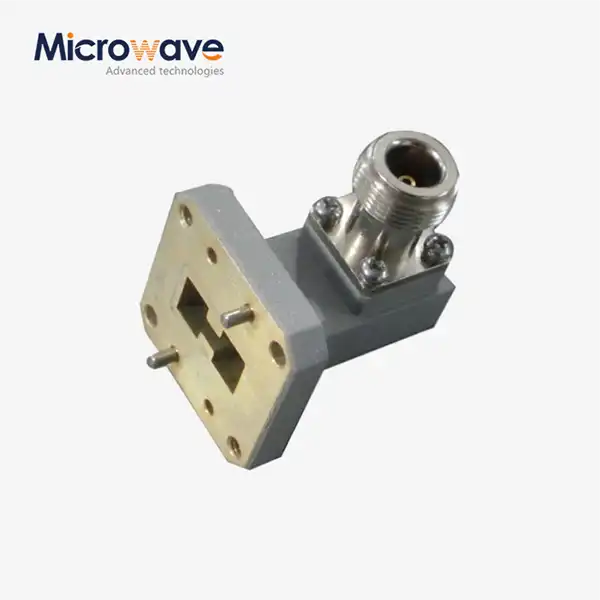
Right Angle Double Ridged WG To Coaxial Adapter
Right Angle Double Ridged WG To Coaxial Adapter
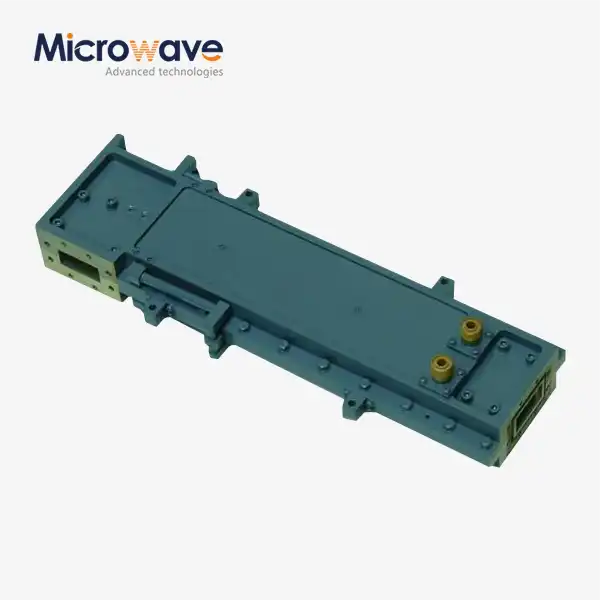
A double-ridged waveguide interface (WRD series) and a coaxial connector can be connected at a right angle with the Right Angle Double Ridged WG To Coaxial Adapter. Advanced Microwave Technologies (ADM) makes these adapters for frequencies between 6 and 18 GHz and 18 and 40 GHz. They come with different types of flanges and coaxial connectors, such as SMA, N-Type, TNC, and SC. Before being sent out, full-band VNA sweep testing is done on each unit to make sure it works properly in defence, test, and radar uses.
Why the Double-Ridged Design Extends Usable Bandwidth of Right Angle Double Ridged WG To Coaxial Adapter?
This double-ridged shape differs from traditional rectangular waveguides in that the electric field is in the middle of the guide. This reduces the cutoff frequency and the waveguide impedance. This allows the device to operate over very large bandwidths which often encompass many octaves.
Depending on the WRD standard, the bandwidth ratio goes up to 2.4:1 or 3.6:1. This is much higher than what normal rectangular guides can handle. This means that test engineers can use a single adapter to cover a wide range of frequencies without having to switch out hardware between steps of the measurement process.
There is a clear technical need for the 90-degree orientation. Coaxial cables can run perpendicular to the waveguide axis. This is needed in places like ECM pods, rack-mounted defence platforms, and tight avionics bays where space along the waveguide axis is limited.
Key Electrical and Physical Properties
Parameter | Specification |
Frequency Range | 6–18 GHz / 18–40 GHz (WRD series) |
VSWR | < 1.30:1 across full band |
Insertion Loss | < 0.3 dB |
Impedance | 50 Ohm (coaxial interface) |
Bandwidth Ratio | 2.4:1 or 3.6:1 |
Connector Types | SMA, N-Type, TNC, SC |
Body Material | Aluminum 6061-T6 or Copper alloy |
Surface Finish | Chromate conversion, Silver or Gold plating |
Plating Standard | MIL-G-45204 / MIL-DTL-5541 |
Configuration | Right Angle (90°) |
Waveguide Series | WRD650, WRD750 and others |
The ridge geometry lowers waveguide impedance to closely match the 50-ohm coaxial line, keeping VSWR below 1.30:1 across the entire operating band rather than only at spot frequencies.
Materials and Construction
The bodies of Right Angle Double Ridged WG To Coaxial Adapter are made from aluminium 6061-T6 or copper alloys, which were chosen because they carry electricity well, are easy to machine, and keep their shape under mechanical and thermal stress.
For chromate conversion coatings, surface finishing must be done according to MIL-DTL-5541. The thickness of the plating is checked against MIL-G-45204 norms. Silver or gold finishing stops oxidation and lowers skin-effect losses over a longer period of time.
The center conductor probe, which is the transition pin, is seated at an exact depth in relation to the ridge. Precision tools are used by ADM to keep the probe in place while it is being put together. Probe placement is the most sensitive part of the build process because even small changes in depth or angle can cause VSWR spikes across the band.
Application Scenarios
Electronic Warfare (EW) and ECM Systems
Airborne jamming pods need to be able to change frequencies across several octaves without having to change their hardware between missions. The right-angle shape fits into small avionics bays and allows for continuous broad-band sweeps.
Broadband EMC and EMI Test Labs
When test engineers connect high-power broadband amplifiers to horn antennas inside of anechoic chambers, they can use a single adapter that works with a wide range of frequencies. This means that fewer changes need to be made to the setup between test runs.
Radar Warning Receivers (RWR)
These adapters move signals from waveguide antennas on the outside to coaxial processing units inside defence systems. Low insertion loss (< 0.3 dB) keeps the signal from getting worse at the changeover point, which is important for finding threats early on.
Quality Control Process
Before sending out any Right Angle Double Ridged WG To Coaxial Adapter, ADM checks each one through an organised QC process.
VNA Full-Band Sweep: A Vector Network Analyser is used to test each unit across the full frequency range that was given. This checks for VSWR and insertion loss and marks any resonance issues that might be caused by mistakes in the manufacturing process.
Mechanical Tolerance Inspection: The dimensions of the edge gap and the flatness of the flange are checked to make sure they are within the acceptable ranges needed for proper impedance matching and preventing arcing.
Verification of Plating Thickness: The thickness of the silver or gold plating is measured and checked against the standards of MIL-G-45204. Non-conforming plating speeds up oxidation and raises resistance losses.
Environmental Stress Screening: Units are put through thermal shock cycles and vibration tests to see how strong the coaxial center conductor bond is in real-life working conditions.
Customization and Support
ADM lets you make your own configurations based on the needs of your system. You can choose from different WRD flange profiles, different types of coaxial connectors, vacuum-compatible versions with vented connectors and low-outgassing dielectrics, and different plating finishes.
The testing center at ADM has a microwave darkroom that is 24 meters long and covers frequencies from 0.5 GHz to 110 GHz for RF proof. For questions about integration, reviewing tolerances, and setting up things in a way that works best for an application, engineering help is available. Use the information below to get in touch with ADM and talk about a custom request.
FAQ
Q: What's the difference between this and a regular rectangular waveguide adapter in terms of power handling?
A: The double-ridged waveguide has a smaller ridge gap than a regular rectangular guide, which makes it able to handle less peak power. Most of the time, the coaxial connector, not the waveguide body, sets the practical power limit in configurations with coaxial connections.
Q: Why do you want a right-angle orientation instead of an end-launch orientation?
A: The right-angle orientation is chosen so that the parts can fit together properly. By letting the coaxial wire exit perpendicular to the waveguide, it is possible for the waveguide to mount flush against a chassis panel or when there isn't much room along the waveguide's axis.
Q: Can these adapters work in places where there is no air flow?
A: Versions that work with vacuums are available, but they need to be customised. To stop virtual leaks and multipaction discharge, they use connections with vents and dielectrics that don't let much gas out.
Q: How do you figure out a WRD adapter's bandwidth?
A: Bandwidth is set by the ridge profile of the WRD standard in question (for example, WRD650, WRD750). Higher-order waveguide modes are blocked by the double-ridged structure, which makes the single-mode usable bandwidth wider than what standard rectangular guides offer.
Q: How important is the level of the transition pin seating?
A: The depth and angle of the probe in relation to the ridge have a direct effect on the VSWR across the band. Precision tools are used by ADM to set and lock the probe position during assembly so that the required VSWR performance is met.
Q: What kinds of connectors are there?
A: You can choose from SMA, N-Type, TNC, and SC coaxial interfaces. You can get custom connector configurations if you ask for them.
Contact Us
For specifications, custom orders, or technical questions about Right Angle Double Ridged WG To Coaxial Adapter, reach ADM at craig@admicrowave.com.
YOU MAY LIKE
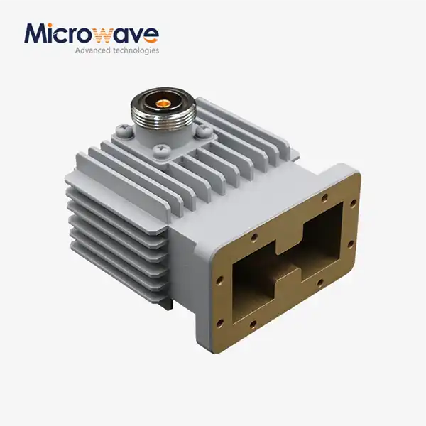 VIEW MOREHigh Power Waveguide to Coaxial Adapter
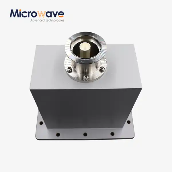 VIEW MOREEnd Launch Waveguide to Coaxial Adapter
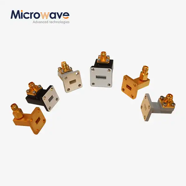 VIEW MORERight Angle Waveguide To Coaxial Adapter
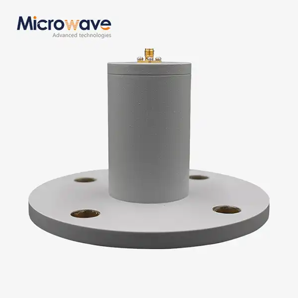 VIEW MORECircular Waveguide To Coaxial Adapter
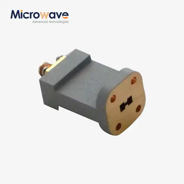 VIEW MOREEnd Launch Double Ridged WG To Coaxial Adapter
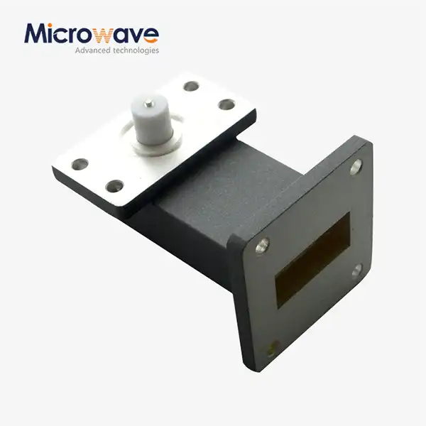 VIEW MORERight Angle Waveguide to Microstrip Adapter
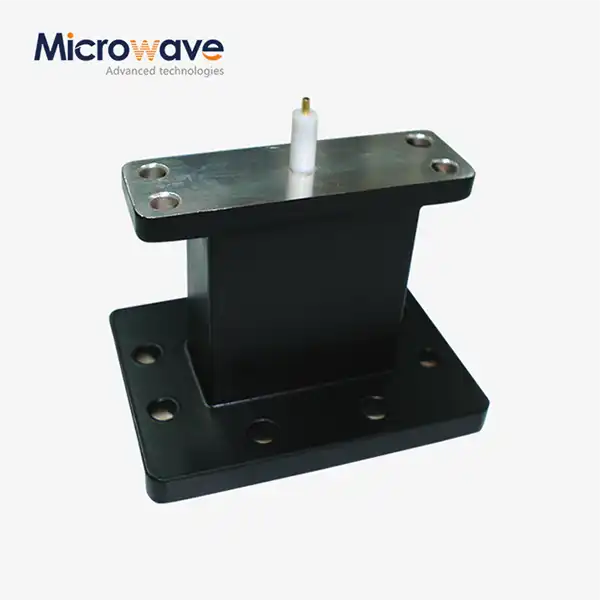 VIEW MOREEnd Launch Waveguide to Microstrip Adapter
 VIEW MOREHigh Power Waveguide Differential Phase Shift Circulator
