




Which Launch Type Suits Double Ridged Waveguide To Coaxial Adapter?
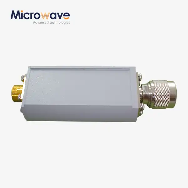
There is a double ridged waveguide to coaxial adapter that works best for most broadband projects. In the ridge gap, you should put an electric probe that is tapered or stepped. The case is small; it plugs into the main power source directly, and it works with common coaxial connectors. An integrated ridge-gap transition is a good choice for projects that need very low VSWR, more power, tight phase repeatability, or direct OEM integration. A magnetic loop can only be used when space or field coupling makes it impossible to use a probe. I think you should match the launch to the environment, power level, frequency range, and connector. Then, use measured RF data to be sure you made the right choice.
Start with the Core Question: What Does "Launch Type" Mean?
Definition of a Launch
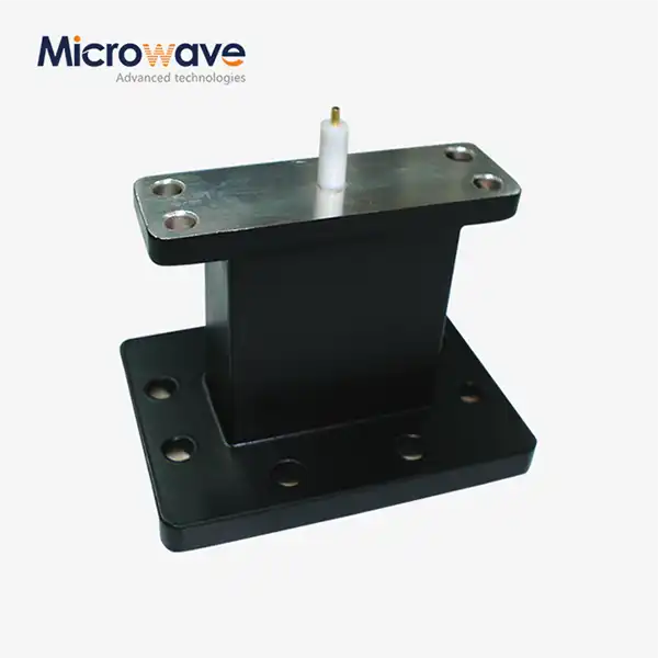
A launch is the part that moves RF energy from a coaxial connector to the waveguide. In a double ridged waveguide to coaxial adapter, this adapter transforms the coaxial TEM mode into the waveguide's main mode. The shape of the center pin, the location of the backshort, and the dielectric support all have an effect on this conversion. These details decide how to match the impedance, mode conversion, insertion loss, and VSWR. It wastes signal and power by sending it back to the source when the launch fails. A well-built launch spreads power evenly across the whole band. That's why I see the launch as the most important part of the adapter and not just an extra for the connector.
Why Ridges Change the Launch Design
A square waveguide has ridges that go all the way to the middle, making a small space. Because of this gap, the electric field is focused, and the cutoff frequency goes down. S. B. Cohn wrote about these things in 1947, and S. Hopfer released design data for ridged guides in 1955. This makes a big band for making calls. The names make it clear what they're for: WRD650 works from 6.5 to 18 GHz, and WRD750 works from 7.5 to 18 GHz. You need to launch from a spot with a strong field close to the ridges so that you can use this guide. Because of the shape of the ridge, the launch size is set. Why? Because a probe made for a simple square guide won't give the same match.
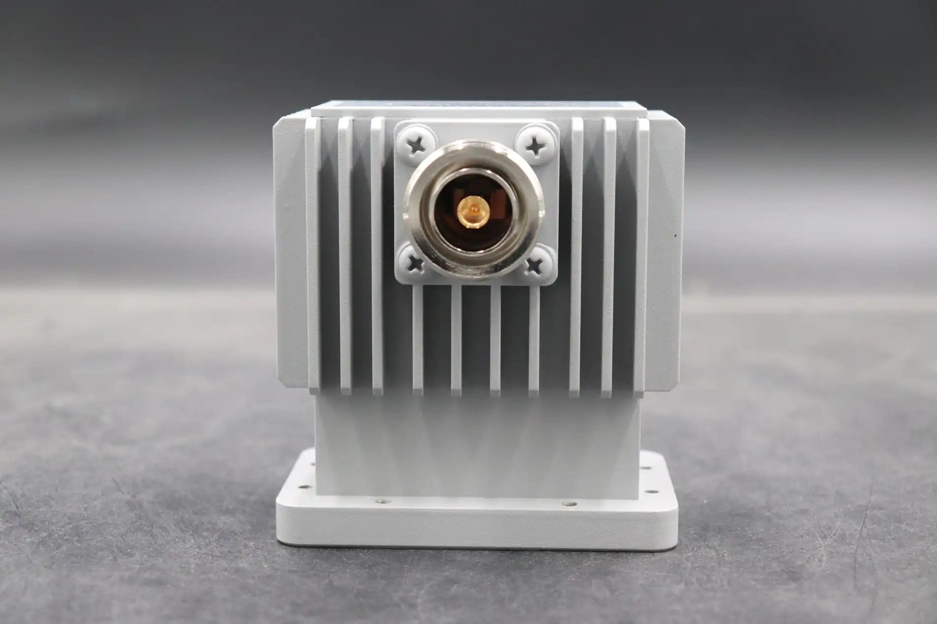
The Four Main Launch Families
There are four main ways that engineers do things. An electric probe is used to put the coaxial center conductor in the ridge gap. For a smoother change, a probe with steps or a tapered end changes the pin's shape more slowly. The magnetic field is linked to a magnetic loop instead of the electric field. A ridge-gap transition makes the probe, ridges, backshort, dielectric, and housing all part of the same unit. It takes more work and better performance to tune each method, but none of them are easy to use. You should think about more than just the connector when making your choice. You should also think about the frequency range, connector type, power level, mechanical space, and RF targets. Coming up, we'll compare them one by one.
Compare Launch Types for Double Ridged Waveguide to Coaxial Adapters
Electric Probe Launch
For a double ridged waveguide to coaxial adapter, people pick the electric probe most of the time. The ridge gap has a strong electric field, and the coaxial center conductor is directly linked to it. Costs and lead times are kept low by making it easy, small, and quick to machine. The length, width, and distance of the probe from the backshort are used to make the match. When the operating band isn't too narrow, or the VSWR target isn't too strict, a simple probe works well. Over a very large range, a simple probe can show resonances. A shaped probe is often used when engineers need smooth performance from one end of the band to the other.
Tapered or Stepped Probe
More of the sharp breaks that cause reflections are smoothed out by a stepped or tapered probe. Not all at once, but in stages, the pin's diameter changes. This makes it work like a general impedance transformer. Broadband matching is possible with this method, and it can be used for test, EMC, radar, and instrumentation systems. It costs more because the design needs more work. It's important to be very precise with every step because even small changes in diameter or length can mess up the match. An engineer can guess what will happen before they cut the metal with the help of simulations. People often ask me what kind of probe they should get if they want a wide band like 2 to 18 GHz in one unit.
Magnetic Loop and Integrated Ridge-Gap Launch
A magnetic loop is linked by the magnetic field. However, it is harder to tune and doesn't happen very often. When it does, it can be useful for field coupling or mechanical placement. There is a built-in ridge-gap launch that goes in a different direction. They are all made to work with each other: the probe, the ridges, the backshort, the dielectric support, and the housing. Some custom systems need to work reliably and well, like ones that need to repeat amplitude or phase very closely. This method works well for those systems. Engineers have to spend more time and measure more. If a regular probe can't do the job, I suggest this one. It's not the first choice for every project.
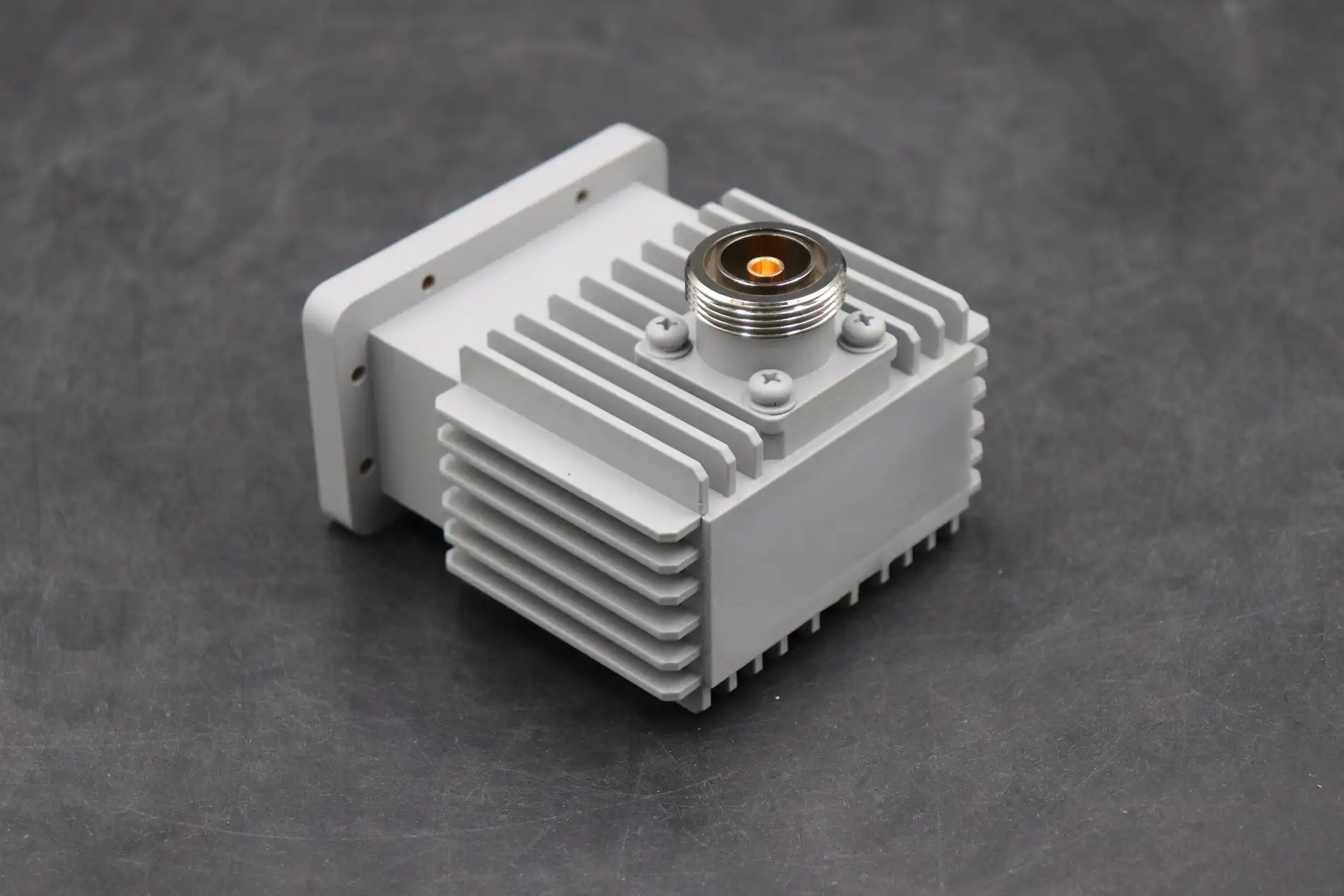
Select the Right Launch by RF Performance and Application
Begin With Frequency Range and Guaranteed Performance
First, the frequency range. The usable band depends on the probe's shape, the size of the ridges, the shape of the connector, and how the cutoff works. It's not enough to trust a WRD label. Labels may be different from one supplier to the next, so make sure you get the drawings, frequency range, and diameter of the flange. Most of the time, MIL-DTL-3922 standards are used for flanges, and MIL-C-39012 standards are used for the coaxial side. Also, check the highest frequency that the connector can handle. If the connector stops at a lower frequency, the adapter won't work. When the system is put together, things don't go wrong because there are written rules for the whole band.
Check VSWR, Insertion Loss, and Power
A number that is very important for a double ridged waveguide to coaxial adapter is mode purity, VSWR, return loss, insertion loss, and impedance. VSWR should be less than 1.5:1 and insertion loss should be less than 0.5 dB across the band, but every model is different. Power needs to be looked after. Most of the time, the coaxial connector can't handle as much power as the waveguide. High-power systems should also be checked for arcing, heat expansion, pulse conditions, and derating. The electric field should also be checked at the ridge gap. Details about how things work are also important. Things like flange flatness, connector concentricity, and machining tolerances can change repeatability. To get the exact production setup, ask for measured RF curves.
Match the Launch to the Application
Broadband double-ridged horn antennas are used in test and EMC setups. To make them work best, they need shaped probes or built-in transitions that keep the VSWR stable and let the calibration be done again and again. Electronic and radar weapons often need to be made to last, be able to handle more power, be sealed, and have a record of inspections. SATCOM feed networks like layouts that aren't too big and don't move around a lot. A custom integrated launch might be a better choice because OEM modules have limits on things like mounting, cable routing, and housing size and shape. It's important to check the materials, plating, temperature limits, and whether they can work with pressure or vacuum in harsh environments. To use a thermal vacuum, make sure the connectors are vented, and the finishes don't give off a lot of gas.
Use a Practical Decision Process and Avoid Common Mistakes
A Four-Step Selection Process
When the process is structured, there is less technical and supply risk. To begin, you should talk about the whole interface, such as the coaxial connector, the impedance, the orientation, and the gender. Second, set RF goals for phase stability, power, frequency, VSWR, and insertion loss. Third, think about the mechanical and environmental needs, like size, material, temperature, vibration, and sealing. Fourth, compare the engineering costs, lead times, testing, and support over the product's lifecycle of standard, custom, and OEM options. After that, you should ask for test reports, conformance certificates, S-parameter files, and dimensional records. It's too late to redesign in this order because each step makes the options for the next step smaller.
Compare Against Alternative Adapters
Teams often choose a double ridged waveguide to coaxial adapter when they need to test RF over a large area and in a number of different ways. A single-ridge guide gives you more coverage and a more even field most of the time, but it is easier to machine a double-ridge guide. As well, it's not the same as a waveguide flange adapter, which joins two waveguide interfaces together. Square WR and WRD flanges don't match up with each other because the bolt patterns and sizes are different. You might save money on a narrower-band adapter if you only need one band. Make sure you don't automatically buy the widest product type. Instead, match the product type to the real operating range.
Mistakes That Cost Time
Most people make the mistake of choosing an adapter based only on its frequency label. This might lead to a lot of VSWR, loss, or the wrong interface. It's also wrong to judge the probe by itself. What makes it work is how well the ridge gap, backshort, flange, and housing all work together. Third, some buyers don't rate for timing, duty cycle, airflow, height, or direction when the power is high. Fourth, buyers do sometimes compare suppliers based only on price. What happens depends on how well the plating is done, how consistent the machining is, how the inspections are done, the technical support, the warranty, and the lead time. You can avoid most of these issues if you make a short list before you buy.
How a Specialized Manufacturer Supports Your Final Choice
Final Recommendation by Launch Type
I begin with an electric or tapered probe that is well-tuned in the double-ridge gap when I need to use broadband. It's about right in terms of coverage, small size, ease of manufacture, and working with common coaxial connectors. When the project needs very low VSWR, a lot of power, tight phase repeatability, better performance in harsh environments, or direct OEM integration, you should use an integrated ridge-gap transition. There are field-coupling or mechanical limits that can be used to make an exception for a magnetic loop. These can be backed up by simulations and tests. Make sure that the measured RF data, interfaces, power, environment, and documentation are all correct before giving the launch the go-ahead. Until the needs show that it needs more, this rule makes sure that the design is simple.
Engineering Support and Rotary Joint Experience
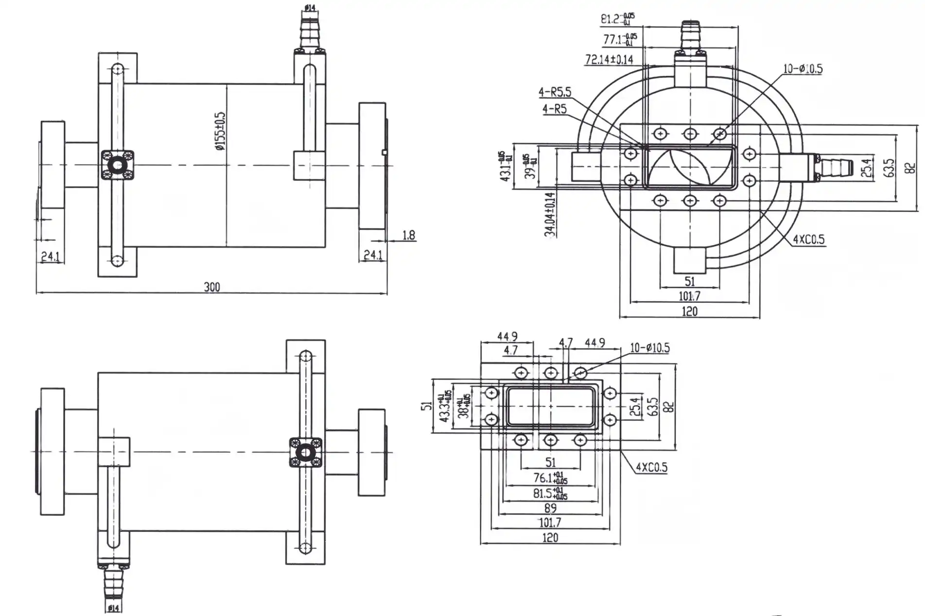
This company, ADM, has been making microwave products for over 20 years. We have measuring tools in our labs that can work with frequencies up to 110 GHz. We make our Double Ridge Waveguide Rotary Joints with what we know about ridged waveguides. These move microwave energy from a line that doesn't move to a line that does move. Because it is made of silver-plated copper, the ADM-500DRWRJI can work with frequencies between 5 and 18 GHz, has a VSWR of 1.5, an insertion loss of 0.5 dB, and an average power of 100 W. The ADM-250DRWRJI can work from 2.6 to 7.8 GHz with 200 W. We offer OEM services that let you change the design, the material, and the frequency range. These services are in addition to prototyping and technical support.
Quality Checks Worth Requesting
Talk to any supplier about how they check each unit. It is helpful to use a vector network analyzer to do full-band sweeps to look for resonance spikes. On a coordinate measuring machine, the flange flatness and ridge gap tolerance must be checked, as well as the pin depth and concentricity. XRF thickness analysis and salt-spray testing must also be done for plating, according to MIL-STD-202. Our goods are approved by ISO 9001 and RoHS, and we carefully check the quality of each order. Find out how much your order weighs so that your engineers can compare it to the specs before it is sent out.
Conclusion
In order to handle mode conversion, insertion loss, impedance matching, and VSWR, the launch type of a double ridged waveguide to coaxial adapter is what makes it work well. Electric probes are common and simple to use. Broadband matching is smoother when probes are tapered or stepped. For certain coupling or space limits, magnetic loops are used, and integrated ridge-gap transitions work best for hard custom projects. As you make your choice, the guaranteed frequency range should be the first thing you look at. Following that, you should think about VSWR, loss, power, mechanical tolerance, the environment, and the type of use, like test, radar, SATCOM, or OEM modules. There is less risk when you know about common mistakes and follow a structured process. For most broadband needs, a tapered or stepped probe that has been tuned well is a good place to start. If your needs are more strict, an integrated design is the best choice. Any choice you make should be backed up by paperwork and measured RF data.
FAQ
Q1: What limits power handling in a double ridged waveguide to a coaxial adapter?
The coaxial connector is the limit these days because the waveguide structure can handle more power than the coax interface. Make sure the frequency, duty cycle, and altitude derating are all right before you finish the design.
Q2: Can I use a standard WR flange with a WRD adapter?
No, WR and WRD flanges can't be put together without a certain transition. The reason for this is that they are not all the same size and shape of bolt. Before you place an order, you should always check your drawing to see what kind of flange it shows.
Q3: Why is VSWR harder to control across a very wide band?
It's more difficult to match impedance over a large octave range than over a small one. With a shaped probe and careful tuning, VSWR stays in the range that was given. See if you can get measured curves to be sure.
Q4: Does ADM offer custom designs?
Yes. When you work with us as an OEM, you can change the design, the material, and the frequency range. We can also help you with the technical side of your project and make prototypes.
Request a Double Ridged Waveguide to Coaxial Adapter Recommendation from ADM
Our engineers will help you choose a standard or custom double ridged waveguide to coaxial adapter if you email craig@admicrowave.com with your frequency range, target VSWR, connector, flange, power level, and quantity. Additionally, we are ISO 9001 certified and make double ridged waveguide to coaxial adapters. There are also RoHS rules that we follow. We deliver quickly and have great customer service after the sale.
References
1. Proceedings of the IRE, 1947 – "Properties of Ridge Wave Guide" by S. B. Cohn
2. IRE Transactions on Microwave Theory and Techniques, 1955 – "The Design of Ridged Waveguides" by S. Hopfer
3. Microwave Engineering (4th Edition), Wiley, 2011 – David M. Pozar
4. Foundations for Microwave Engineering (2nd Edition), Wiley-IEEE Press, 2001 – Robert E. Collin
5. Waveguide Handbook, McGraw-Hill, 1951 – Nathan Marcuvitz
6. MIL-STD-202, Test Method Standard for Electronic and Electrical Component Parts, U.S. Department of Defense, 2015