





Waveguide Variable Attenuator Applications in Radar and SATCOM Testing
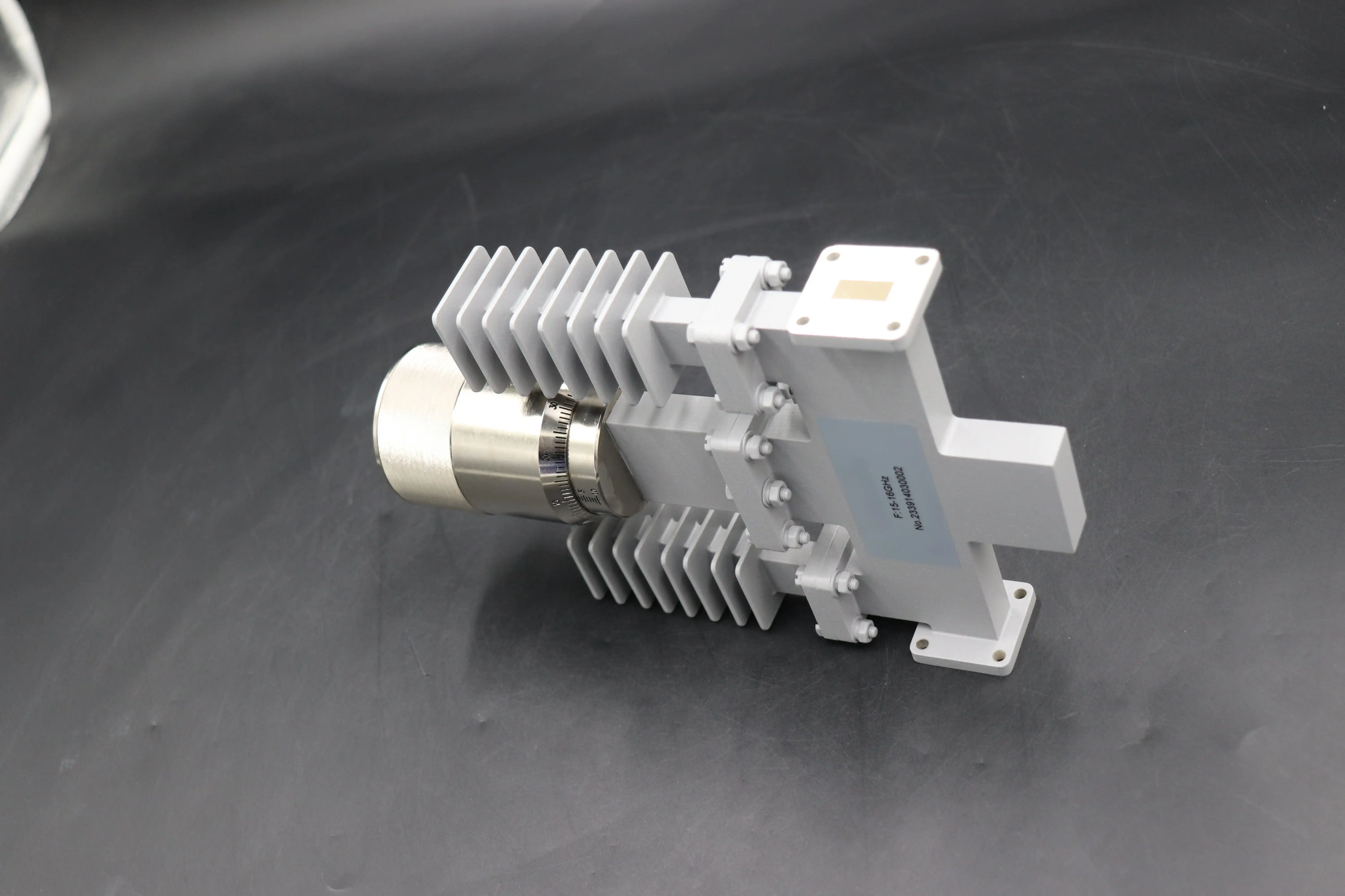
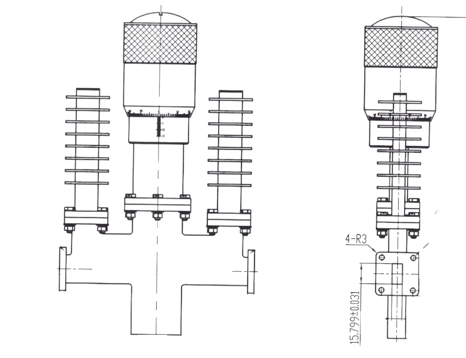
A waveguide variable attenuator is a high-precision microwave component that controls signal amplitude within a waveguide transmission line — without interrupting the signal path. In radar and SATCOM testing, these devices allow engineers to adjust attenuation continuously, typically from 0 dB up to 60 dB or beyond, by inserting a resistive vane into the electric field of the waveguide. This controlled insertion loss protects sensitive receivers, enables accurate calibration, and simulates real-world signal conditions. Their superior power handling and low VSWR performance make them the preferred choice over coaxial alternatives in high-frequency test environments.
Understanding Waveguide Variable Attenuators in Radar and SATCOM
What Makes These Devices Different From Fixed Attenuators
Fixed attenuators lower the signal by a set amount that can't be changed. They're good for training static signals but can't be used for dynamic tests. Engineers can set a precise attenuation value on the fly with a variable type. When calibrating radar receivers or simulating rain fade in SATCOM links, this level of flexibility is very important. Sweeping through an attenuation range without switching out components cuts down on test time and mistakes made by humans by a large amount.
Core Technical Parameters You Need to Know
Frequency range, attenuation range, insertion loss, and VSWR are the most important parameters that describe effectiveness. The WR-90 model works with the X-band (8.2–12.4 GHz), and the WR-28 model works with the Ka-band (26.5–40 GHz). When set to 0 dB, residual insertion loss stays below 0.5 dB most of the time. VSWR stays below 1.15:1 across the whole range of attenuation levels in quality units. This keeps echoes to a minimum, which would otherwise throw off test results. Modelers that are driven by micrometers can get as accurate as 0.01 dB.
Why Waveguide Outperforms Coaxial at High Power
In waveguide structures, signals travel through a metal cavity filled with air. This design does not need a middle wire like coaxial designs do. Since this isn't there, there is no risk of dielectric breakdown when the power is high. Waveguide attenuators can handle high power levels of kilowatts, which is common in burst radar applications. Coaxial attenuators, on the other hand, would fail electrically or thermally at those levels. This difference has a direct effect on system safety and the long-term durability of gear for defense and aircraft acquisition teams.
Core Applications in Radar and SATCOM Testing
Radar Receiver Sensitivity and Calibration
Radar systems need receivers that can pick up very weak return signals. In order to calibrate a receiver, experts send a known signal level to the front end and then check the output. The supplied power level can be changed step by step with a variable resistor, which accurately maps the receiver's dynamic range. IEEE standards for radar measurement say that signal level control must be within ±0.5 dB for receiver sensitivity tests. Good waveguide variable attenuators always meet this requirement.
Simulating Signal Fading in SATCOM Ground Stations
Atmospheric attenuation affects satellite transmission links, mostly at Ku-band and Ka-band frequencies. In warm and mid-latitude areas, rain fade can add 10–20 dB of extra path loss. During system qualification, engineers at the ground station add a variable attenuator to the signal chain to make this fading happen again. This lets the adaptive coding systems and link budget management software be tested before they are put into use, which lowers the chance of communication problems during operational service.
Power Leveling and Protection in High-Frequency Test Setups
Test benches that have signal generators, amplifiers, and sensitive measurement devices need to handle power very carefully. Without attenuation control, the output of an amplifier can easily overload downstream parts, which can damage low-noise amplifiers or mess up measurements from a vector network analyzer (VNA). Putting a waveguide variable attenuator between the source and the device being tested creates a buffer that can be controlled. This protects expensive equipment and keeps measurements accurate across a wide frequency range.
Selecting the Right Waveguide Variable Attenuator: Key Criteria for Procurement
Matching Frequency Band and Waveguide Size
There is a clear frequency band for each common waveguide size. The buying teams need to make sure that the attenuator's waveguide interface works with the current system's ports and frequency of operation. The waveguide interface could be WR-90, WR-62, WR-28, or another standard. When interfaces don't match, they need adapter parts that add more insertion loss and possible reflection points. You can avoid this problem by getting a unit from a single batch that covers the whole working band of your radar or SATCOM system.
Evaluating Attenuation Range, Resolution, and Drive Mechanism
The attenuation range and resolution needed for a test application are different each time. Direct-reading drum-scale models are easy to use, while micrometer-driven models have a higher resolution and are better for tasks that need to be repeatable to within 0.01 dB. Motorized models with stepper motors and GPIB, USB, or Ethernet interfaces can be used with automated test equipment (ATE). These models allow for remote, script-controlled attenuation sweeping, which is very useful in production test environments for increasing productivity.
Procurement Factors: MOQ, Lead Time, and Customization
Aside from specifications, actual procurement factors also play a role in sourcing choices. Before making an order, expert buyers should think about the following things:
- Waveguide interface compatibility: Confirm flange type (UG, FBP, or custom) to prevent integration delays after delivery.
- Motorized vs. manual drive: Automated test lines generally require motorized units; lab benches may work fine with manual models, reducing per-unit cost.
- Customization documentation: OEM buyers often need detailed calibration charts, test reports, and traceability documentation for system-level integration and quality audits.
- Lead time and MOQ flexibility: Suppliers who accommodate prototype quantities alongside production orders give procurement teams the ability to validate performance before committing to volume.
If you think about these things early on in the buying process, you can avoid expensive design changes and problems with the supply chain later on in the project cycle.
Best Practices and Successful Testing Scenarios
Radar Calibration Accuracy Improvement
A defense electronics installer testing an X-band radar receiver said that changing from a waveguide variable attenuator to a waveguide variable attenuator in the WR-90 band cut the error in the calibration from ±1.2 dB to ±0.3 dB. The attenuator's lower VSWR and higher return loss made things better by getting rid of standing waves that were causing measurement scatter before. This kind of proven performance gain makes the higher unit cost of waveguide-based solutions worth it for procurement engineers who are choosing test tools for radar projects.
SATCOM Ground Station Qualification
Engineers put a motorized waveguide filter into the receive chain and simulated 15 dB of rain fade while testing the Ka-band ground station. The GPIB interface controlled the automated attenuation sweep, which finished a full fade profile test in less than 10 minutes. Previously, this process took over an hour of manual component swaps. The repeatability over 50 test runs showed fluctuation below 0.05 dB, which met the system integrator's requirements for qualification.
Installation and Maintenance Tips
Long-term attenuator performance is directly affected by how well it is installed and how often it is serviced. If you are an engineer or technician, remember these things:
- Flange torque: Follow manufacturer torque specifications for flange fasteners. Over-tightening distorts the waveguide aperture; under-tightening allows signal leakage.
- VNA inspection intervals: Periodic insertion loss and return loss checks with a vector network analyzer catch resistive vane degradation from oxidation or contamination early.
- Mechanical drive inspection: Check micrometer or motorized drive mechanisms for smooth, consistent movement. Thread seizure on manual drives is the most common failure mode in high-use lab environments.
By following these rules, you can make the attenuator last longer and keep its measurement accuracy over its whole life.
Future Trends in Waveguide Attenuator Technology
Transition Toward Automated and Programmable Solutions
Fully automated benches are becoming more common in the test and measurement business. Software-defined test platforms can now directly connect to programmable waveguide attenuators that have standard digital interfaces. With this change, radar and SATCOM test engineers can now write automatic test scripts that check power levels, record system replies, and make compliance reports—all without any help from a person.
Advances in Materials and Miniaturization
Attenuators are getting better at blocking higher millimeter-wave frequencies, like W-band (75–110 GHz), thanks to research into low-loss, resistant materials and precise cutting. Tighter manufacturing tolerances allow for smaller form factors, which support small radar and SATCOM test modules in places where bench space is limited. Because ADM can measure up to 110 GHz in-house, the company is ready to help clients working at these high-frequency bands.
Growing Demand Across Defense and Commercial SATCOM
With hundreds of low Earth orbit (LEO) satellite systems going into service, the world market for satellite communications is growing very quickly. Every new ground port and package needs to be qualified, which keeps the demand for precise microwave test components high. If procurement planners can find reliable waveguide attenuator suppliers now, they will be better able to support faster program schedules in the future.
Conclusion
Waveguide variable attenuators are essential tools in radar and SATCOM testing, offering precise signal control, high power handling, and low VSWR performance that coaxial alternatives cannot match at microwave and millimeter-wave frequencies. From receiver sensitivity calibration to rain fade simulation and automated ATE integration, selecting the right component directly influences the accuracy and reliability of your test results. For procurement teams and engineers sourcing for defense, satellite, or research applications, understanding these technical and logistical factors leads to better decisions and fewer surprises during system integration.
FAQ
What is the difference between a variable and a fixed waveguide attenuator?
A fixed attenuator delivers one set attenuation value and cannot be adjusted. A variable type allows continuous or stepped adjustment across a defined range — typically 0 dB to 30 dB or higher — making it suitable for calibration, sensitivity testing, and dynamic test scenarios where signal levels must change during the test procedure.
Which frequency bands do these attenuators support for radar and SATCOM?
Standard waveguide sizes cover all major bands used in radar and satellite communications. WR-90 covers X-band (8.2–12.4 GHz), WR-62 covers Ku-band (12.4–18 GHz), and WR-28 covers Ka-band (26.5–40 GHz). ADM supports frequency ranges up to 110 GHz in-house.
Are motorized versions available for automated test equipment?
Yes. Motorized waveguide attenuators with stepper motors and GPIB, USB, or Ethernet interfaces are standard for ATE integration, allowing remote, script-controlled attenuation sweeping.
Can custom configurations be ordered?
Yes. Custom flange types, attenuation ranges, and calibration documentation are available. OEM buyers with specific tolerance or documentation requirements should contact the supplier directly to discuss project needs.
What peak power levels can waveguide attenuators handle?
Depending on the waveguide band and design, peak power handling can reach kilowatts — a key advantage for pulsed radar applications where coaxial designs would fail due to voltage breakdown.
Get Precision Waveguide Attenuators From ADM — Trusted Waveguide Variable Attenuator Supplier
A fixed waveguide variable attenuator only provides a single attenuation value and can't be changed. A variable type can be set to a certain range, usually 0 dB to 30 dB or higher, and can be adjusted continuously or step-by-step. This makes it good for calibration, sensitivity testing, and dynamic test situations where signal levels need to change during the test. Reach out to our engineering team at craig@admicrowave.com to talk your frequency range needs and receive a quote.
References
1. Pozar, D. M. — Microwave Engineering, 4th Edition, Wiley, 2011.
2. IEEE Standard 686 — IEEE Standard Radar Definitions, IEEE, 2017.
3. Skolnik, M. I. — Radar Handbook, 3rd Edition, McGraw-Hill, 2008.
4. ITU-R P.838 — Specific Attenuation Model for Rain for Use in Prediction Methods, ITU, 2005.
5. Barker, R. J. & Schamiloglu, E. — High-Power Microwave Sources and Technologies, IEEE Press, 2001.
6. IEEE Transactions on Microwave Theory and Techniques — Volume 68, Issue 9, IEEE, 2020.
YOU MAY LIKE
 VIEW MORECoaxial Power Detector
 VIEW MOREWG Transition
 VIEW MORECircular Waveguide Transition
 VIEW MOREDouble Ridged WG To Coaxial Adapter
 VIEW MOREPlastic Flange Caps
 VIEW MOREDual Linear Broadband Circular Polarization Horn Antenna
 VIEW MOREPyramidal Linear Polarization Horn Antenna
 VIEW MOREQuadrifilar Helix Antenna