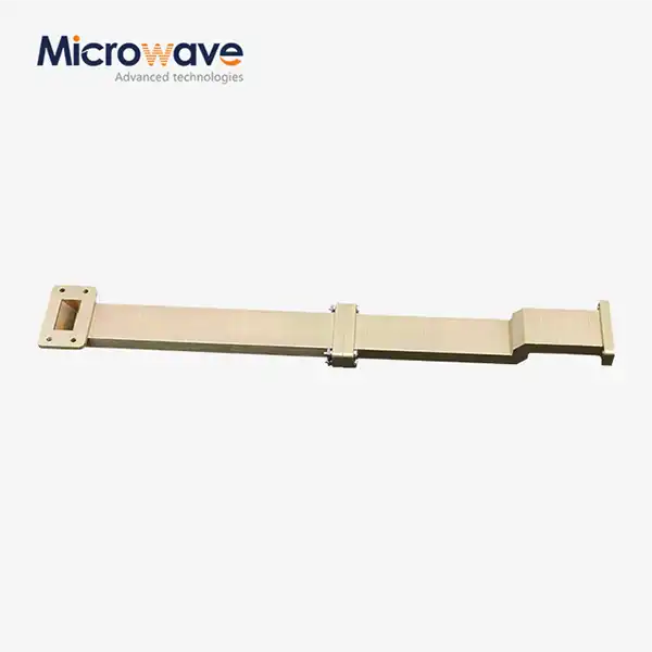
WG Transition
WG Transition for Waveguide Systems — Precision-Engineered Solutions for Microwave Applications
Advanced Microwave Technologies (ADM) makes WG Transition components that can be used in both standard rectangular designs and custom multi-band configurations from 0.5 GHz to 110 GHz. Different shapes of waveguides are supported, such as rectangular, flat rectangular, medium flat rectangular, square, circular, single ridge, and double ridge. ADM has been working as a microwave engineer for more than 20 years and provides transition solutions for uses in satellite communication, aerospace, and precise measurement.
What Is a WG Transition?
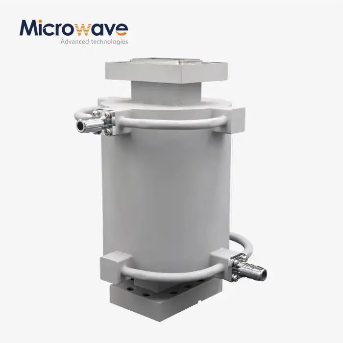
A waveguide transition is a passive microwave element that is used to connect two waveguide sections of different shape, size, or kind of transmission lines. It modifies the manner in which signals propagate across structures and minimises distortion of signals and power loss.
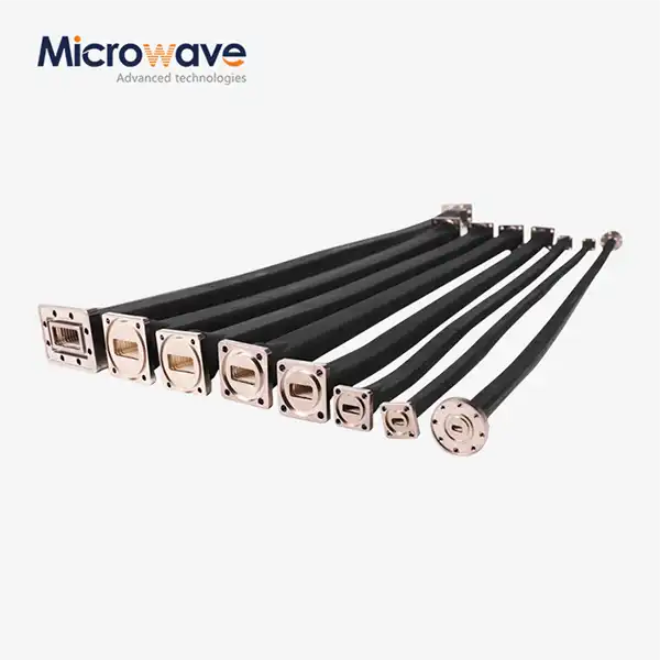
In actual life, one can make transitions to couple square waveguides to round ones, to couple standard waveguides to flat ones, or to couple ridge waveguides to coaxial lines. Each configuration calls for careful geometric engineering to preserve the signal integrity across the intended frequency band.
Supported Waveguide Types and Configurations
ADM's product line has a lot of different physical configurations, which lets engineers match parts to different system designs.
Types that are supported are:
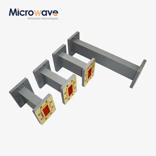
· Rectangular waveguide transitions — standard overlapping band designs
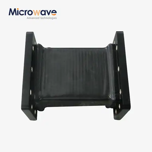
· Flat rectangular and medium flat rectangular — space-saving profiles for compact assemblies
· Square waveguide transitions — for symmetric mode propagation
· Circular waveguide transitions — commonly used in rotary joints and antenna feeds
· Single ridge and double ridge waveguide transitions — for extended bandwidth operation
All types are available with standard or custom flange configurations. Custom multi-band transitions spanning extended frequency ranges are also supported.


Technical Specifications
Parameter | Specification |
Frequency Range | 0.5 GHz – 110 GHz (customizable) |
Waveguide Types | Rectangular, Flat Rectangular, Medium Flat, Square, Circular, Single Ridge, Double Ridge |
VSWR | < 1.10 (over operating bandwidth) |
Insertion Loss | Typically < 0.05 dB |
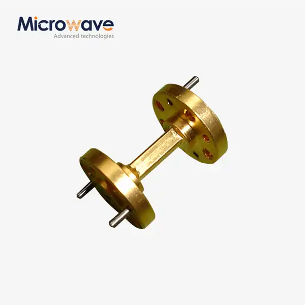
Surface Treatment | Silver (Ag) or Gold (Au) plating available |
Material Options | Oxygen-Free Copper (OFC), Aluminum (6061-T6), Brass |
Flange Standard | Custom or standard flange interface |
Customization | Available per user requirements |
Pressure Sealing | Supported for pressurized applications (nitrogen/dry air) |
Have specific requirements not listed above? Send your specifications to the ADM engineering team for a technical review.
Materials and Surface Treatment
The choice of material for the WG Transition has a direct impact on signal loss, weight and long-term reliability. ADM uses three basic materials depending on application requirements.
Oxygen-Free Copper (OFC) is the greatest conductor for high power, low loss applications. Aluminium 6061-T6 has a strong weight to performance ratio for aerospace and satellite equipment. Brass is a hard metal and can be used for ground measurement equipment.
The interior of a device is usually plated with Silver (Ag) or Gold (Au) to minimise resistive losses especially at high frequencies. Gold polishing also offers chemical passivation which slows oxidation and minimises intermodulation distortion over time. This is particularly handy for pressured or out-of-doors deployments.
Key Performance Characteristics
Low VSWR: ADM's transitions keep VSWR below 1.10 across the operating band. This lowers the amount of power that is reflected and protects the parts further upstream.
Low Insertion Loss: Insertion loss is less than 0.05 dB, which means that signal intensity is maintained at the transition interface. This is important for signal chains with numerous stages.
Pressure Sealing: If necessary, modifications are made to keep the internal pressure using nitrogen or dry air. This prevents spark arcing in high power gearbox systems.
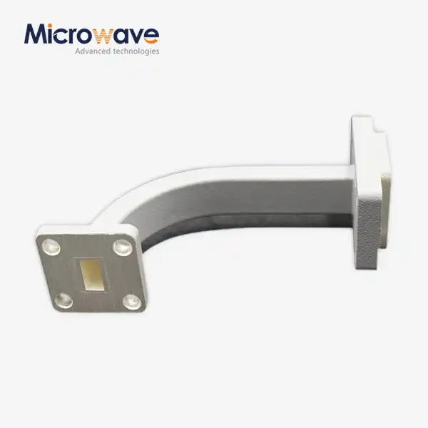
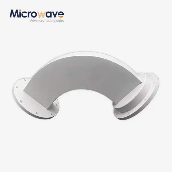
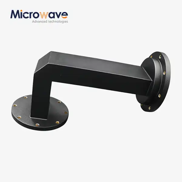
Swept or Mitered Geometry: Transitions can be achieved with swept (radius) forms for reduced reflection or mitered profile for less space needed in installation depending on system needs.
Applications
Satellite Communication: In satellite payloads and ground stations, transitions are utilised to connect feed horns, diplexers and waveguide lines. Stable signal behaviour over high bandwidths is needed for long distance communications.
Aerospace and Defence: Lightweight aluminium transitions for radar, electronic warfare and airborne communication systems are engineered to provide low system weight and meet stringent mechanical and electrical tolerances.
Microwave Measurement: Precision transitions are utilised in VNA calibration setups and antenna test systems. The 24-meter microwave darkroom from ADM is suitable for near and far field testing up to 110 GHz.
Advanced Communication Systems: 5G backhaul, point-to-point links and millimeter-wave systems require transitions with controlled dispersion and low return loss over vast frequency ranges.
Quality Control and Testing
All ADM WG Transition developed is subject to a rigorous testing process before release. Testing is performed by measuring S-parameters using a Vector Network Analyser (VNA), which measures insertion loss (S₂₁) and return loss (S₁₁). Return loss objectives are better than -20dB in passband. Flange alignment and internal geometry restrictions are verified by dimensional inspection.
For very high power or pressure versions, the sealing quality is examined to make sure that the part can hold the pressure inside without leaking. S-parameters are available on request.
Customization Options
ADM supports full customization of waveguide transition designs based on customer technical requirements. Engineers can specify:
· Waveguide type and cross-sectional geometry
· Frequency band and bandwidth requirements
· Flange interface standard
· Material and surface plating selection
· Pressure sealing requirement
· Multi-band transition spanning extended frequency ranges
Contact the ADM engineering team with your specifications to request a technical review and quotation.
FAQ
Q: What kind of waveguides are available for the transition products of ADM?
A: ADM can be used for rectangular, flat rectangular, middle flat rectangular, square, circular, single ridge and double ridge types of waveguides. Custom settings can be done based on the demands of the system.
Q: What frequency can your waveguide transitions handle?
A: ADM can test and produce devices from 0.5GHz up to 110GHz. Transitions can be constructed for specific sub-bands, or for a large band range that meets the need.
Q: Does ADM provide custom waveguide transitions for many bands?
A: Yes. ADM produces unique multi-band transitions that can operate over greater frequency ranges than conventional single-band systems. Give the engineering team your technical needs and they will determine if it is even achievable.
Q: What kind of material should I use for an aerospace project?
A: Aluminium 6061-T6 is utilised commonly in aircraft applications because of its strength to weight ratio. Fixed ground based systems are made with Oxygen-Free Copper (OFC), which offers the best conductivity.
Q: How is the performance of VSWR checked before it is shipped?
A: Each transition is tested with a Vector Network Analyser. Check VSWR is less than 1.10 over the rated operational bandwidth. S parameter data can be supplied on request.
Q: Are you involved with pressurised waveguide transition assemblies?
A: Yes. ADM produces pressure sealed transitions that maintain nitrogen or dry air pressurisation, preventing arcing at high power radio frequency transmission sites.
Contact Us
Have a technical question or need a custom WG Transition? Reach the ADM engineering team at craig@admicrowave.com.