





How Wide Can a Double Ridge Transition Band Really Go?
A double ridge transition can work with more than one octave, most of the time at 3:1 or 4:1 ratios. A normal rectangular waveguide only gives you about 40–50% of the range you need. The scale is shown by the numbers: WRD-650 covers 6.5–18 GHz, and WRD-180 covers 18–40 GHz. But there isn't just one number that stops you. The range that can be used is affected by VSWR, insertion loss, the coaxial connector, the tolerances of the machine work, and the flange interface. This guide was written for engineers and buyers who need to make decisions about double ridge transitions based on how well they work, not on the datasheet's widest span.
What Is a Double Ridge Transition and How Does It Work?
Why the Operating Range Is Not a Single Number
A lot of people ask me for one frequency span. I can't give you one because a double ridge transition is not just a waveguide section; it's an entire group. The useful range is determined by the frequency limits, VSWR, return loss, insertion loss, power handling, type of connector, and waveguide interface. Theoretical electromagnetic coverage tells you where a signal can travel through a waveguide. When you measure something in real life, usable coverage tells you where the assembly meets your acceptance limits. There is a big difference between the two. This is a problem for antenna test teams, EMC labs, radar programs, and microwave integrators. To fix it, I suggest setting acceptance criteria first, then comparing datasheets.
Construction and Common Interfaces
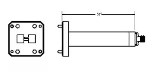
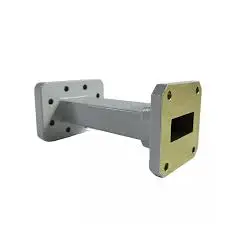
Another double ridge transition links a coaxial line with a TEM signal to a double-ridged waveguide with a TE10-type mode. These are the main parts: the waveguide body, the ridge profile, the ridge gap, the tapered section, the connector, and the flange. SMA, 2.92 mm, and 2.4 mm connectors are common types of coaxial interfaces. A double ridge flange is used on the waveguide side. Here, compatibility is important. Standard UG or CPR flanges are not the same as double ridge flanges like the FPWRD series. That's why I always check the WRD number to make sure the bolt pattern and alignment pins match.
How Ridges and Taper Shape Performance
The ridges carry the weight. They make the next higher-order mode higher and lower the cutoff frequency of the fundamental mode. This creates a large single-mode region in a small body. After that, the taper slowly changes the impedance from the 50-ohm coaxial line to the frequency-dependent impedance in the ridge gap. A taper that is longer and smoother tends to reduce reflection, but it also adds length and a little loss. Changes in mode control, taper length, waveguide dimensions, and ridge geometry can all change insertion and reflection loss. That's why a nominal frequency span can't help you choose a product by itself.
How Wide Can a Double Ridge Transition Band Really Go?
Practical Range Categories
I put designs into four main groups: ultra-broadband, narrowband, octave-band, and multi-octave. A normal square waveguide is in the narrowband group, and it can only be used in 40–50% of the range. A double ridge design goes into the territory of multiple octaves, where 3:1 or 4:1 ratios show up. In real life, the WRD-650 ranges from 6.5 to 18 GHz, and the WRD-180 ranges from 18 to 40 GHz. Why this is important can be seen in electronic warfare and broadband testing. One well-matched transition can cover a much larger part of the range (6–40 GHz) than three separate waveguide setups. However, the exact coverage will still depend on the design.
What Sets the Lower and Upper Edges
The lower edge is based on how the cutoff works, the shape of the ridges, how well the connector launches, and the mechanical size. If the ridges are deeper, the cutoff is lower. If the gaps are smaller, the electric field is more concentrated, and the peak power capacity is cut. Higher-order modes, machining tolerances, surface finish, connector capability, and radiation leakage are some of the most common reasons why the upper edge breaks. VSWR spikes often show up when I work outside the single-mode region of a ridge profile. The same problem can happen if the center-conductor probe is not positioned in the middle of the ridge gap. There should be separate checks for a clean low end and a clean high end.
Judging Usable Range Against Acceptance Criteria
I tell people not to just look at the span that is advertized as being the widest. They should also test the numbers that really matter, like VSWR, insertion loss, amplitude flatness, phase response, mode purity, and production repeatability. There are a lot of double ridge transitions that keep the VSWR below 1.30:1 or 1.50:1 across the whole band, but your system may need more control. A change that is 1.50:1 across 6.5–18 GHz might work for a monitoring path but not for a calibrated measurement setup. First, set your pass/fail limits. Then, compare the response curve to those limits.
How Is Double Ridge Transition Performance Verified?
Specifications to Request
In a datasheet, the frequency range, VSWR, return loss, insertion loss, phase response, power rating, temperature range, and details about the interface should all be written down. Ask what kind of connector it is and what the flange is called, like the WRD number. There are four main things that quality teams look at: a full-band VSWR and insertion-loss sweep, ridge-gap tolerance, plating adhesion with surface finish, and power handling for military lots. Under MIL-STD-202, thermal shock testing can be part of plating checks. Ask for measured response curves instead of just normal curves; this way you can check the unit against your own limits of what is acceptable.
Measurement Practice
The quality of the measurement tells you whether you can trust a number. Check the connectors, use the right flange torque, inspect the vector network analyzer with the right waveguide calibration, and keep the cable from moving. When the reference plane is different from the transition face, de-embedding can get rid of fixture effects. Check S11 for reflection and S21 for loss. Also, look out for moding or spikes, which can show problems with the way the part was machined on the inside. When putting together a system, measured Touchstone files are helpful because simulation tools can directly import them. At ADM, our labs use microwave measurement tools that go up to 110 GHz, which is a lot higher than the WRD-180's 40 GHz top end.
Tolerances, Materials, and Common Deviations
It is the ridge gap that is the most sensitive because it controls the impedance. A coordinate measuring machine with micron-level accuracy is often used by quality control to check it. A body made of aluminum 6061, copper, or brass plated with silver or gold reduces ohmic loss, and chromate coatings keep them from rusting. When you use a lot of power, rough surfaces can cause arcing. Tolerances, assembly gaps, material differences, and measurement uncertainty are some of the main reasons why simulation and measurement don't always match up. If you want to compare products, you should only do so under the same calibration, temperature, torque, and reference-plane conditions. This is because results that aren't matched up correctly can be misleading.
Double Ridge Transition vs. Other Transition Technologies
Versus Rectangular Waveguide
For standardized bands, narrowband operation, and high-power systems, the rectangular waveguide is still the better choice. It can handle more peak power than a ridged guide because its field is not squished into a small gap. A rectangular band can only cover about 40–50%, so you need more than one setup for a wide sweep. Some peak power is given up in exchange for wide coverage in a double ridge transition. If your system only works in one standard band, I suggest a rectangular waveguide. If you need to cross several bands without swapping hardware, I suggest a rigid option.
Versus Coaxial and Single-Ridge Options
Even though coaxial transitions make it easy to connect cables, the connector and launch design still decide what can and can't be done. Different interfaces, like SMA, 2.92 mm, and 2.4 mm, can handle different highest frequencies. This means that the assembly can only go as fast as its weakest interface. The double-ridge waveguide-to-coaxial transition can handle more power than the coaxial cable by itself. However, the final rating is limited by the connector that is attached, which can be SMA or N-type. Single-ridge guides have a middle path that isn't as wide as double-ridge guides. Pick a technology based on your needs for band, size, mode control, loss, and calibration, not on how well-known it is.
Application-Specific Priorities
Applications change what's most important. Antenna measurement ranges need to have low reflection, stable phase, and consistent mounting. Test engineers use these changes to connect VNA coaxial cables to wideband gain horns so that the calibration stays the same over wide sweeps. Broad coverage and strong construction are important for EMC and EMI systems. Low loss, pulse capability, thermal control, and peak power are all important for radar and electronic warfare systems, such as airborne jamming pods. Ground stations for satellites can connect the outputs of traveling wave tube amplifiers to coaxial monitoring paths. Small mechanical errors can cause loss very quickly at millimeter-wave frequencies, so accuracy in dimensions and alignment is more important.
How to Select the Best Double Ridge Transition for Your Application?
Define Band, Limits, and Guard Band
Make a list of the lowest and highest frequencies your system needs. Then, add an engineering guard band to make sure that edge performance doesn't decide whether the system passes or fails. The next step is to choose the connector and flange and set limits for VSWR and insertion loss. Don't pay for span that isn't being used; extra coverage can add cost and complexity. I put stable VSWR, insertion loss, phase behavior, and repeatability ahead of raw coverage when measurement accuracy is very important. You can rate things like price, lead time, supply continuity, range, interface, size, environment, documents, and more with a weighted comparison table.
Environment and Documentation
Before you ask for a quote, make sure you know the limits for power, temperature, vibration, humidity, vacuum, and installation. For vacuum use, you need a part that is made for thermal vacuum and has holes in it to let air escape. Materials and finishes that don't outgas should also be avoided. Then ask for inspection records, measured S-parameters, compliance documents, drawings, CAD files, and information about the materials. The products made by ADM are ISO 9001 certified and RoHS compliant. For OEM programs, you should also look at revision control, traceability, production inspection, lead time, and long-term supply stability. This is because a good prototype doesn't mean much if it can't be made again and again.
When a Custom Double Ridge Transition Makes Sense
A part from a catalog might not work if you need bands that aren't standard, connectors or flanges that aren't standard, tight packaging, strict VSWR targets, high power, vacuum operation, or thermal cycling. Send your question about a specific range of frequencies, loss limits, interfaces, power, environment, CAD data, quantities, and schedule. In most cases, the process starts with a technical review and then moves on to simulation, CAD design, prototype, VNA testing, validation, and production. OEM services, quick prototyping, and technical support from engineers who can help with setup and fixing problems are all things that ADM can do.
Conclusion
A double ridge transition can cover more than one octave, usually at ratios of 3:1 or 4:1. However, the range that can be used depends on the whole assembly, not just the advertized number. Ridges lower the cutoff and make single-mode operation last longer. The taper matches the coaxial line to the gap between the ridges. The lower and upper limits are set by the weakest connector or flange, higher-order modes, tolerances, and the surface finish. VSWR, insertion loss, phase response, and S-parameter measurements taken under consistent calibration show how well the device really works. A rectangular waveguide works best for single bands and higher power, while a rigid design works best for wide sweeps. By setting acceptance limits first and adding a sensible guard band, you can avoid paying for span that isn't being used.
FAQ
Q1: Is there a universal frequency range for a double ridge transition?
No, the range depends on the shape of the ridges, the interfaces, the tolerances, and the limits of your VSWR and loss. To give you an idea, WRD-650 works at 6.5–18 GHz and WRD-180 works at 18–40 GHz.
Q2: Why do I see VSWR spikes at specific frequencies?
A center-conductor probe that isn't lined up right with the ridge gap is often what causes spikes. You may also see them if the operating frequency goes above the single-mode range of that ridge profile.
Q3: Can I use one in vacuum, and which documents should I request?
Yes, if the part is made for a thermal vacuum and has holes for airflow and materials that don't let gas escape. Ask for test curves, datasheets, drawings, S-parameters, material details, inspection records, and certificates of compliance.
Request a Double Ridge Transition Recommendation or Quotation
You need a double ridge transition manufacturer who can read your drawings and answer your technical questions if you want to start a project. ADM can look at your frequency range, VSWR and insertion loss limits, the type of connector or flange you have, the power level, the environment, the quantity, and the schedule. You can get a catalog, CAD model, performance data, or quote by emailing craig@admicrowave.com for more information. Under ISO 9001 quality control, our engineers help with standard selection, prototyping, and OEM production.
References
1. Microwave Engineering, 4th Edition, Wiley, 2011
2. Properties of Ridge Wave Guide, Proceedings of the IRE, 1947
3. The Design of Ridged Waveguides, IRE Transactions on Microwave Theory and Techniques, 1955
4. Foundations for Microwave Engineering, 2nd Edition, Wiley-IEEE Press, 2001
5. MIL-STD-202H, Test Method Standard: Electronic and Electrical Component Parts, 2015
6. Microwave Engineering: Passive Circuits, Prentice Hall, 1988
YOU MAY LIKE
 VIEW MOREHigh Power Waveguide to Coaxial Adapter
 VIEW MORERF Power Detector
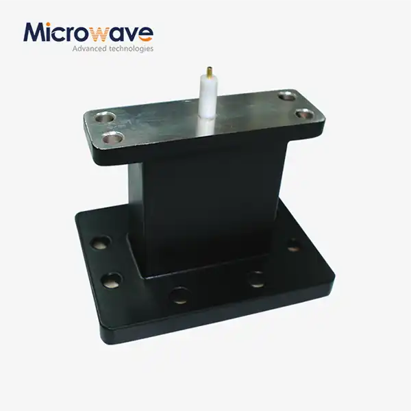 VIEW MOREEnd Launch Waveguide to Microstrip Adapter
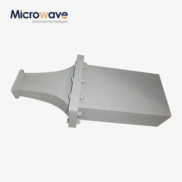 VIEW MOREDouble Ridge Waveguide Termination
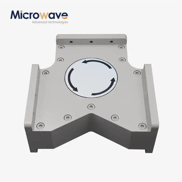 VIEW MOREHigh Power Waveguide Circulator
 VIEW MOREWG High Pass Filter
 VIEW MOREWaveguide Adjustable Support
 VIEW MOREPlanar Spiral Antenna