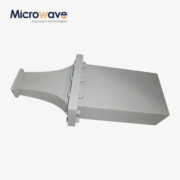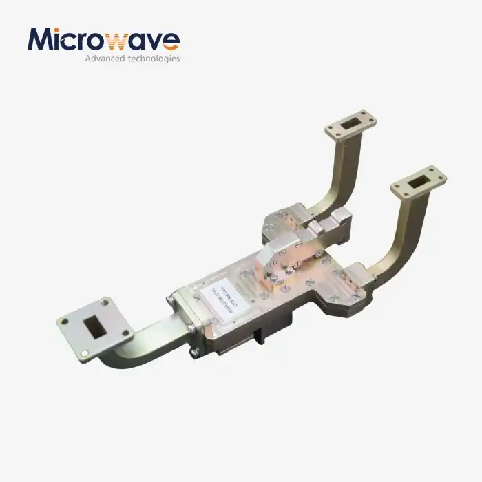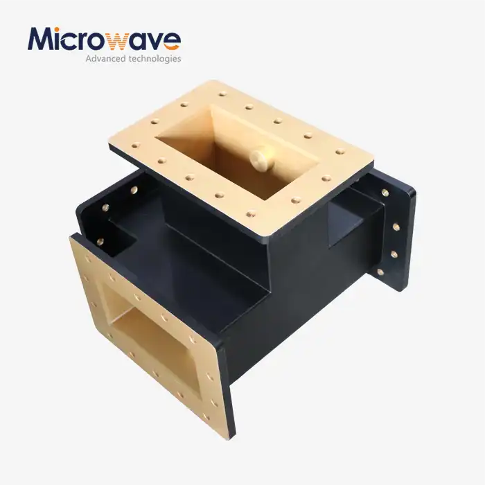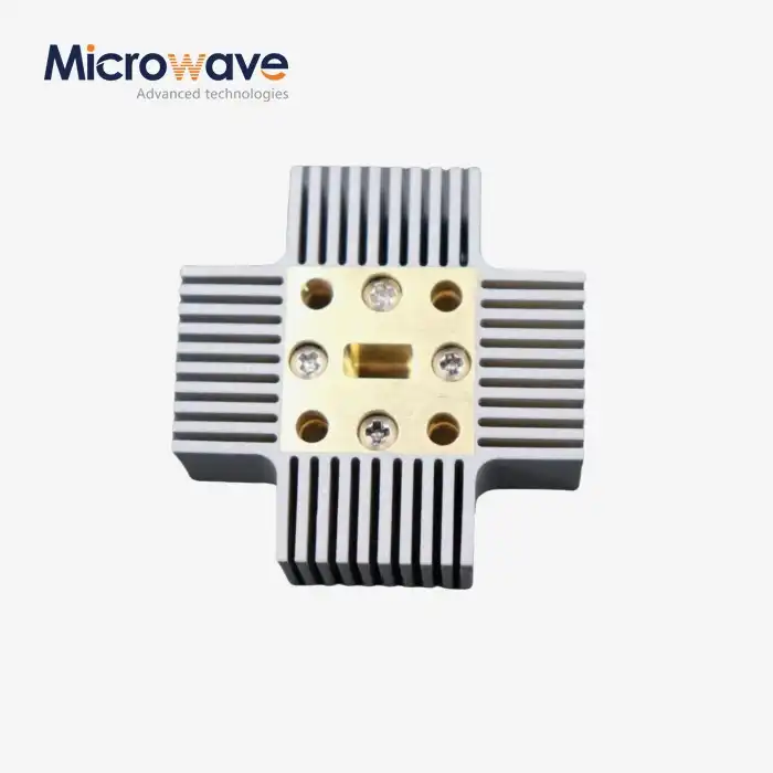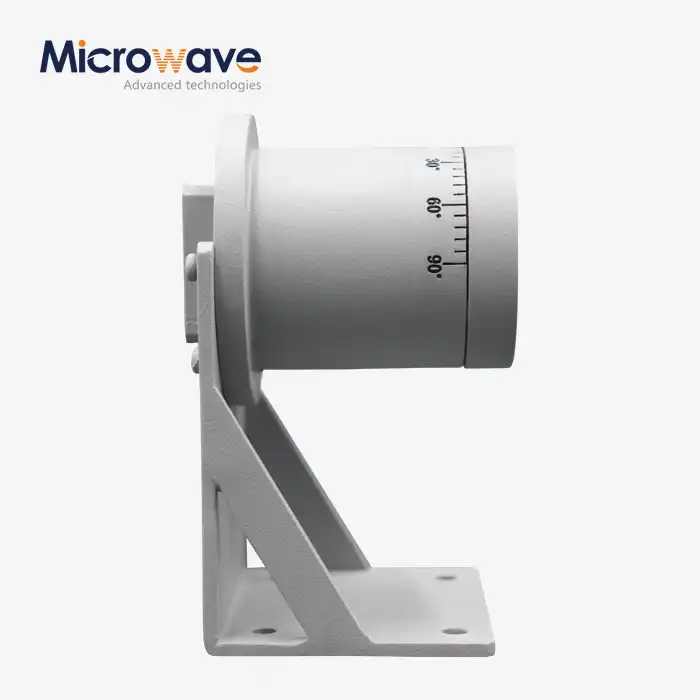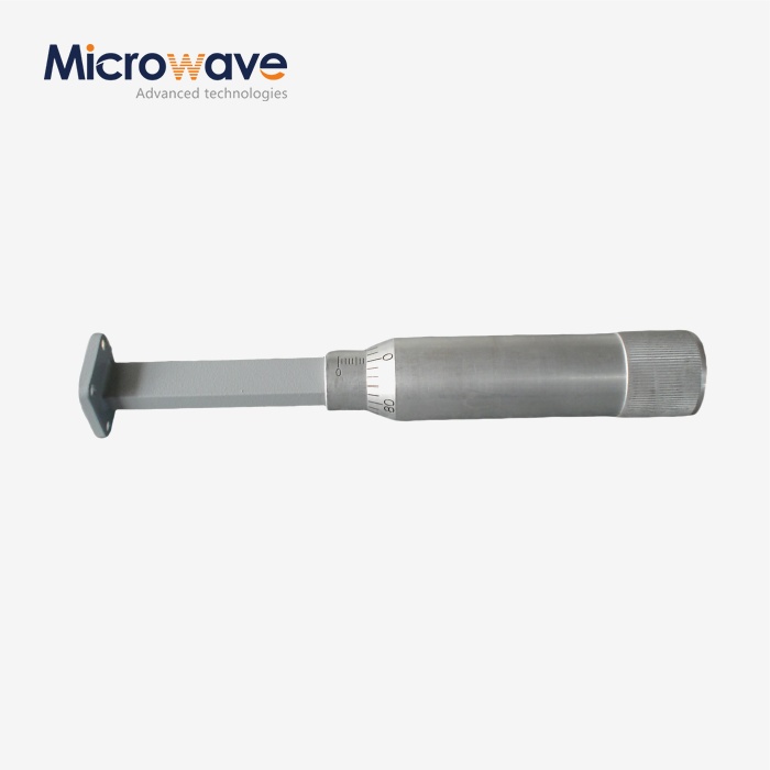

Waveguide Sliding Termination
Waveguide Sliding Termination — Adjustable Phase Load for Microwave Calibration
A Waveguide Sliding Termination is a precise measuring part used for VNA calibration, metrology, and figuring out what a high-frequency system is all about. There is a tapered absorbing element inside that moves longitudinally along the waveguide line. This lets the phase of the residual reflection change while the magnitude stays the same. This flexibility lets engineers separate and get rid of error terms that are caused by load, which is something that set terminations can't do. ADM's standard line has sliding distances of 180° and 360° across a number of waveguide bands.
How It Differs from a Fixed Load: Waveguide Sliding Termination
When you connect something to a fixed termination, there is a static residual reflection that makes it impossible to calibrate accurately. This might be fine for general bench use, but in the Ku, K, Ka, V, and W bands, where machining tolerances have a noticeable impact on performance, the static error term adds a lot of uncertainty.
This problem can be fixed with a sliding termination, which lets the engineer change the phase of the leftover reflection all the time. The reflecting vector of the absorbing element moves along a circle on the Smith Chart. Using math to fit that circle shows the VNA's real direction and source match. This method is called the ripple technique or slide load calibration.
Because of this, sliding terminations are used in SOL and TRL calibration processes when fixed loads would make the measurements too uncertain.
Key Technical Specifications
Parameter | Specification |
Sliding Distance | 180° or 360° phase rotation |
Flange Flatness | Within 0.02 mm |
Power Handling | Low-power signals, typically < 1–5 W |
Absorbing Element | High-loss dielectric wedges (silicon carbide or ferrite) |
Housing Material | Silver-plated brass, aluminum, or OFHC copper |
Plating | Silver or gold to prevent oxidation |
Position Control | Vernier or digital micrometer |
Flange Interface | Per MIL-DTL-3922 |
Waveguide Dimensions | Per IEC 60154 |
Materials and Construction
The consistency of calibration data is directly related to how stable the Waveguide Sliding Termination housing is in terms of its dimensions. The outside of the ADM is made of silver-plated brass, aluminium, or Oxygen-Free High Conductivity (OFHC) copper, which is chosen to keep ohmic losses low across the frequency range it works in.
High-loss dielectric wedges made of silicon carbide or ferrite and machined to a precise taper are used in the absorbing element. The gradual shape creates a smooth impedance change, which means that the reflection coefficient value stays the same as the slide moves.
A vernier or digital micrometre is built into the drive mechanism. Positional repeatability is most important in automated calibration routines where the software needs to go back to positions that have already been logged without adding phase error from backlash in the mechanical parts.
Application Scenarios
VNA Calibration in Metrology Labs
The product is the main tool used to fix the directivity error term in standards-level testing work. Engineers record the reflection data at different points along the slide and then fit the circle to get a calibrated error model. This method gives precision that can't be matched by fixed loads, especially above 40 GHz.
Getting to Know Source Impedance
When engineers set up a load-pull or tuner, the ripple method lets them separate the source reflection coefficient of an active device from the termination's small mismatch contribution. The impedance map is now cleaner, and you don't need any extra hardware to fix it.
Antenna Range and Feed Structure Verification
A Waveguide Sliding Termination helps measure the amount of mismatch uncertainty in the transmitter-to-feed path during the anechoic chamber testing of high-gain antennas. By lowering this uncertainty, the estimated gain numbers will show the real performance when radiated, not just artefacts from the feed line.
Quality Control Process
Before being sent out, each unit goes through a set of checks:
Ripple Test: A swept-frequency measurement over the whole slide journey shows that the change in return loss magnitude stays within the allowed range.
Backlash and Hysteresis Check: The micrometre drive is used in both directions to make sure that the load returns to the same electrical characteristics no matter which way it is approached from.
Flange Planarity Inspection: Optical profiling shows that the surface is flat within 0.02 mm. The thickness of the plating is checked to make sure that the electrical contact at the flange junction is always the same.
Travel Smoothness: The slide path is checked for spots where it sticks or rubs against something, which could move the absorbing element off-center.
Thermal Stability Check: The absorbing element is checked to make sure that its dielectric properties stay the same across the recommended operating temperature range.
Customization and Supply
ADM can make custom configurations for certain frequency ranges, waveguide bands, and flange types. You can choose from sliding distances of 180° and 360°. If your application needs a mechanical form factor that isn't standard, ADM's engineering team can talk about the needs and make sure it's possible before production starts.
ADM's main factory is in Xi'an, and it also has branches in Chengdu, Beijing, Tianjin, and Shijiazhuang. All of its products are made there. We have test equipment that works from 0.5 GHz to 110 GHz in-house.
FAQ
Q: Do you know why you should use a sliding termination instead of a precision set load?
A: Post-processing can't get rid of the static residual reflection that comes from a fixed load. By moving the termination, a group of reflection vectors is created whose circle center shows the real load match. This makes it possible to figure out the error contribution and subtract it from the measurement.
Q: How do you set the lower frequency limit?
A: At the lowest frequency, the slide must be able to move at least one half-wavelength in order to finish a full phase cycle. This means that designs with lower frequencies need longer mechanical housings and are bigger overall.
Q: Can high-power signals go through it?
A: Not really. Low-power measurement signals, usually less than 1–5 W, are what these parts are rated for. When the power level is high, the absorbing element gets hot, which changes its dielectric qualities and makes the calibration less accurate.
Q: In real life, how does the ripple technique work?
A: The vector sum of the source and load reflections moves along a circle on the Smith Chart as the ends move. The true source match or directivity figure is in the middle of that circle. The diameter of the circle is equal to the sliding load's residual reflection size.
Q: In what ways does regular maintenance work?
A: Keep the inside of the waveguide clean and free of oxidation products and dust. Regularly check the micrometre drive to see if it needs to be oiled, but make sure the waveguide cavity stays dry and oil-free to avoid contaminating the dielectric.
Q: Can ADM provide waveguide band configurations that aren't standard?
A: Yes. Get in touch with ADM and let them know your frequency range, flange type, and any technical restrictions. The engineering team will let you know if a normal version will work for you or if you need a custom build.
Contact Us
Send product inquiries or custom configuration requests for Waveguide Sliding Termination to craig@admicrowave.com and ADM's team will respond directly.