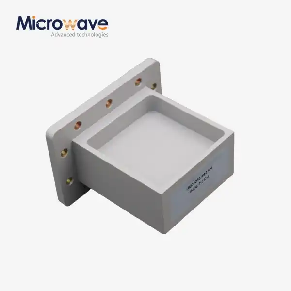
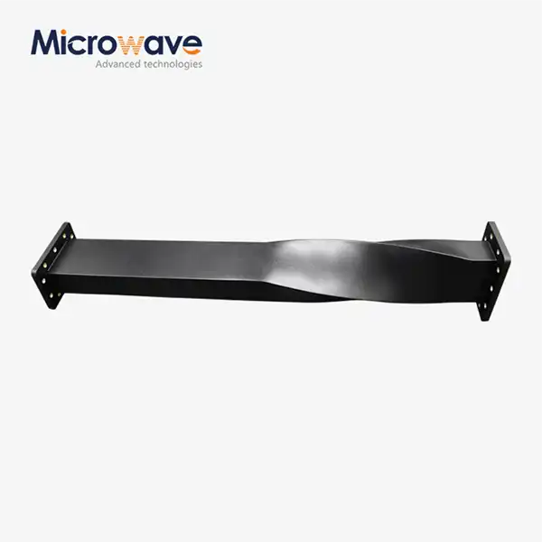
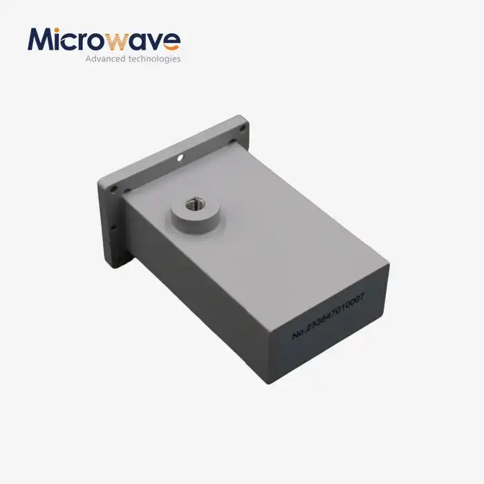
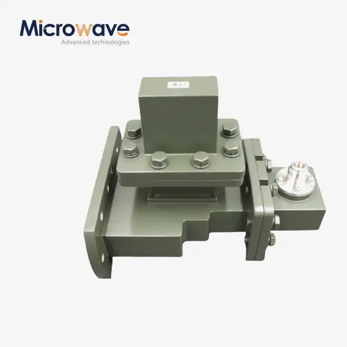
What Are the Design Advantages of an E-Plane Tee?
The E-Plane Tee, also known as a Series Tee, represents a cornerstone of microwave engineering with distinct design advantages that directly impact system performance. This specialized three-port waveguide junction excels in delivering superior power handling, exceptional phase control with its characteristic 180-degree phase difference between collinear ports, and robust mechanical stability. Its unique electric field orientation enables precise signal subtraction in antenna feed networks while maintaining low insertion loss and high isolation. These advantages make it indispensable for mission-critical applications in radar systems, satellite communications, and high-frequency measurement equipment where reliability and precision are non-negotiable.
Understanding the Fundamentals of an E-Plane Tee
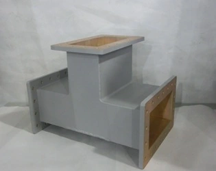
We at Advanced Microwave Technologies Co., Ltd. have spent more than twenty years getting better at understanding waveguide parts. The E-Plane Tee is a special three-port junction with an extra side arm that lines up with the main waveguide's electric field plane. This shape makes what engineers call a "series circuit connection," which is what makes it fundamentally different from its H-Plane cousin.
When electromagnetic energy comes in through the side arm, the part divides it evenly between two ports that are lined up with each other. The 180-degree phase relationship between outputs is what makes this unique. This trait solves difficult signal processing problems without the need for external phase shifters. Because it has built-in phase reversal, the device is perfect for making pattern differences in antenna arrays and monopulse radar systems.
Basic Structure and Operating Principles
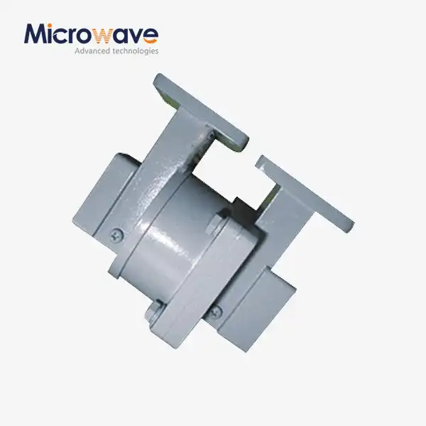
Precision-machined waveguide pieces are joined at right angles to make up the structure. At ADM, we use oxygen-free copper and aluminum alloys with high conductivity, usually 6061-T6 grade, in our manufacturing process. These alloys are then plated with silver or gold to improve conductivity at skin depths. Tolerances for the junction geometry must be kept to the micron level; even small changes can lead to mode conversion and signal degradation.
Key Electrical Parameters
Procurement teams can make better choices when they understand success metrics. In matched designs, the Voltage Standing Wave Ratio is usually between 1.15:1 and 1.3:1. However, basic joints that don't have internal matching structures may show higher values. Insertion loss stays very low, generally less than 0.1 dB across all operating bandwidths. When properly terminated, isolation between collinear ports reaches 20 to 30 dB, which is a key requirement for keeping crosstalk from happening in complex RF architectures.
Frequency Band Specifications
We have standard waveguide bands from L-Band to W-Band in our product lines. For radar uses, X-Band configurations (8.2-12.4 GHz) with WR-90 waveguide dimensions are very common. Ka-Band configurations (26.5-40 GHz) are used for satellite ground station networks. For each frequency range, there are specific flange standards that must be met. UG-style connectors make sure that all foreign systems are pressure-sealed and mechanically aligned correctly.
Core Design Advantages of the E-Plane Tee
The E-Plane Tee's unique benefits have been known by engineers for a long time. By making these parts for defense contractors and telecommunications integrators, we've learned about specific benefits that go straight to system-level benefits.
Superior Power Handling Capabilities
The ability to handle power is a clear advantage over coaxial options. The all-metal waveguide design gets rid of the problems with dielectric breakdown that come with cable assemblies. Standard air-dielectric configurations can handle continuous power levels of more than a few kilowatts. Pressurized SF6 gas variants can handle applications up to a megawatt in size. This feature is very important for industrial microwave heating systems and high-power radar emitters where broken parts cause expensive downtime.
Not having any internal dielectrics also means that there is almost no passive intermodulation distortion, which is very important for sensitive receiver systems and multi-carrier telecommunications equipment. Our tests in ADM's 24-meter microwave lab confirm that PIM works below -160 dBc, which meets strict defense and aerospace requirements.
Exceptional Mechanical Robustness
In tough settings, durability is important. Extreme temperature changes from -55°C to +85°C don't affect the performance of the solid metal design. Parts in shipboard radar systems and aerospace applications are subject to a lot of vibration. Our E-Plane Tees stay the same size even under these stresses thanks to their precise CNC machining and strong flange designs.
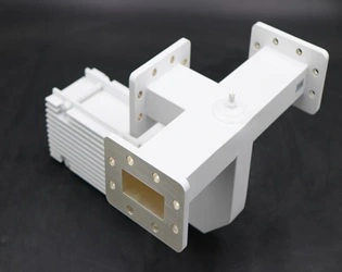
When we make things, we pay extra attention to how resistant they are to corrosion. We use chromate conversion coats and anti-tarnish processes on silver plating to make it last longer in marine and humid industrial settings. Salt spray tests according to ASTM B117 standards confirm performance over deployment rounds that last more than one year.
Compact Form Factor with Space Efficiency
Modern RF systems are getting smaller while adding more features. The perpendicular junction design of the E-Plane Tee takes up much less room than magic tee configurations or spread coupler networks. This small size helps dense phased array installs and satellite payload systems, where each cubic centimeter adds weight and costs money.
Our tech team can change the way mountings are set up to fit different chassis shapes. Threaded inserts, captive hardware, and precision pilot holes make it easy to quickly integrate parts during system assembly, which saves OEM manufacturers money on labor costs.
Low Insertion Loss and Signal Integrity
Signal loss builds up along complicated RF chains. The insertion loss of each component has a direct effect on the noise figure and dynamic range of the system. When properly matched, E-Plane Tees cause very little loss, usually between 0.05 and 0.08 dB across all operational bandwidths. This performance comes from junction shapes that have been adjusted to include inductive posts or capacitive irises that smooth out reactive discontinuities.
To make sure the response curves are flat, we use the Vector Network Analyzer to test across full frequency sweeps. Our ISO 9001:2015-certified quality processes make sure that every unit meets the written standards before it is shipped. This keeps manufacturers from having the problems that happen in the field that happen with less strict processes.
Versatile Customization Options
Not every application is the same. Customized options are available for all waveguide sizes, frequency bands, and flange setups through ADM's OEM services. Teams in charge of buying things can ask for specific port positions, built-in fixing brackets, and plating materials. Our prototyping services can make test units in just a few weeks, so you can quickly see if the design works before it goes into full production.
We can improve VSWR performance for certain frequency sub-bands by using custom matched networks. This adaptability is useful for study groups making experimental systems and defense companies working on secret projects with specific needs.
Comparative Analysis: E-Plane Tee vs. Other Waveguide Tees
Knowing the pros and cons of each type of waveguide junction helps you make better decisions about what to buy. Each structure has its own electric properties that make it useful for different tasks.
E-Plane Tee Versus H-Plane Tee
The main difference is how the phases relate to each other. As shunt connections, H-Plane Tees make outputs that are in phase at ports that are parallel to each other. Because of this, they work great for power merging tasks where signals need to be added in a good way. On the other hand, the 180-degree phase shift of the E-Plane Tee allows signal subtraction, which is what monopulse radar tracking and balanced mixer configurations are based on.
Because the walls in the side arm are farther apart, E-Plane junctions can usually handle more power mechanically. There are big differences in the electric field concentration patterns, which affect the breaking points and the need for temperature control.
Comparison with Magic Tee Configurations
Magic Tees join E-Plane and H-Plane junctions into four-port networks that can send both sum and difference signals at the same time. They are more flexible, but they take up more space and add more insertion loss. The costs of procurement are 40 to 60 percent higher than those of discrete E-Plane or H-Plane parts.
When system designers need both sum and difference channels, they choose Magic Tees. Dedicated E-Plane Tees are easy to use and don't cost much for applications that only need one function.
Performance Metrics Summary
Comparing important specs helps make the selection process clearer:
| Parameter | E-Plane Tee | H-Plane Tee | Magic Tee |
|---|---|---|---|
| Phase Relationship | 180° (opposite phase) | 0° (in-phase) | Both available |
| Typical Insertion Loss | 0.05-0.1 dB | 0.05-0.1 dB | 0.15-0.25 dB |
| Isolation (matched) | 20-30 dB | 20-30 dB | 25-35 dB |
| Power Handling | Very High | High | High |
| Physical Size | Closed | Closed | Big |
| Relative Cost | Low | Low | High |
These measures help engineers find the best answers. Defense radar systems that need to handle different channels naturally prefer E-Plane Tees, while telecoms power combiners usually use H-Plane versions.
Application Scenarios and Industry Use Cases
The E-Plane Tee's usefulness in many different fields is shown by its use in real life. Defense contractors, satellite operators, and research institutions are among our clients. Each of them uses design advantages that are unique to their needs.
Monopulse Radar Tracking Systems
Monopulse radar is the most difficult use case for E-Plane Tees. The part is what the difference channel is made of, and it subtracts data from antenna elements to make angle error information. This makes it possible to keep a close eye on planes and missiles even when there are jamming conditions.
Our X-Band E-Plane Tees were recently added to an upgrade for air traffic control radar by a defense firm we work with. The system can now track with an accuracy of 0.1 degrees and work reliably in conditions with high vibration and extreme temperatures. This performance boost was directly caused by the phase stability of our matched junctions.
Satellite Ground Station Feed Networks
In order to control the polarization and steer the beam, satellite communications need a phase-symmetrical signal distribution. Ground stations use E-Plane Tees to make push-pull amplifier setups and special array feeds that need exact 180-degree phase relationships.
Our Ka-Band parts are used by many ground units that power world phone networks. Low passive intermodulation keeps interference from happening in busy frequency ranges, and high power handling lets kilowatt-class uplink emitters work.
Laboratory Impedance Matching Systems
As series stub tuners, E-Plane Tees with sliding short circuits are used in research and development labs. Engineers can dynamically cancel reactive mismatches in this configuration, which protects sensitive sources like magnetrons and klystrons from damage caused by reflected power.
This setting feature is also useful for industrial microwave heating applications. To get the most energy transfer efficiency out of manufacturing methods that use plasma generation or material treatment, the impedances must be perfectly matched.
Emerging Technology Integration
As we move toward 5G millimeter-wave networks and later 6G systems, new possibilities will open up. E-Plane Tees that work at 28 GHz and higher frequencies make it possible for large MIMO antenna arrays to have small beamforming networks. Our engineering team works with companies that make telecommunications equipment to create next-generation parts that meet the needs of these changing needs.
Environmental sustainability now plays a role in purchasing choices. Our ISO 14001:2015 certification shows that we are committed to reducing the environmental impact of our manufacturing by using energy-efficient methods and getting materials in a responsible way.
Procurement Insights: Selecting the Right E-Plane Tee Supplier
When picking a waveguide component supplier, you need to look at more than just the price quotes. Long-term project success depends on technical know-how, quality control, and the dependability of the supply chain. The E-Plane Tee selection process should prioritize these factors to ensure high system integrity.
Critical Technical Specifications
Procurement engineers should make sure that the frequency range covered meets the needs of the application with enough room for error. Instead of using average values, ask for actual data that shows VSWR and insertion loss across all bandwidths. The scores for peak and average power handling must take modulation features and safety margins into account.
Pay close attention to flange compatibility—make sure that UG-style or other connector standards work with the system interfaces you already have. Mechanical integration difficulty is affected by physical factors such as mounting hole shapes and port orientations.
Quality Certifications and Testing Protocols
Getting ISO 9001 approval means that quality management is being done in a planned way, but you should look into how the tests are actually done. At ADM, swept-frequency Vector Network Analyzer tests are done on all production units up to 110 GHz. Micron-level tolerances are ensured with coordinate measuring tools used for dimension checking.
Material certifications check the composition of alloys and the thickness of the plating. X-ray fluorescence research proves that the silver or gold treatment meets certain standards. This stops corrosion and performance loss before they happen. Ask for proof of conformance along with measurements of the shipped units.
Customization Capabilities and Engineering Support
Standard stock parts don't always work perfectly in unique uses. Check how deep the suppliers' OEM services and tech help go. Our professional team at ADM has more than twenty years of experience with microwaves and can help with installation, system integration, and unique design.
The time it takes to make a prototype affects the plan for growth. We send prototypes in three to four weeks, which lets you make changes to the plan quickly. Production wait times for large orders are usually between six and eight weeks, but can be longer based on how complicated the configuration is.
Supply Chain Reliability and Logistics
When you source from around the world, wait times and quality can vary. ADM's established supply lines and integrated production sites make sure that deliveries are always on time. Our ISO 45001:2018 certification shows that we care about safety at work and lowers the chance of industrial accidents causing problems.
How fine parts are packed and shipped is important. We use custom foam fillers and rigid cases to keep fragile flanges safe while they are being shipped internationally. Full insurance coverage and tracking systems let you see your shipment at all times during the delivery cycle.
Conclusion
The E-Plane Tee has benefits that can't be beaten for uses that need precise phase control, high power handling, and reliable mechanical design. Because of its 180-degree phase connection, it can do important things in radar tracking, satellite communications, and lab measurement systems that other parts can't. It's helpful for procurement teams to know about these design strengths along with practical things like quality standards, the ability to customize, and the dependability of the provider. Advanced Microwave Technologies Co., Ltd mixes years of experience making products with full technical support to make sure that the best parts are chosen and that they can be easily integrated into mission-critical RF systems around the world.
Frequently Asked Questions
What distinguishes an E-Plane Tee from an H-Plane Tee in practical applications?
For signal subtraction tasks like monopulse radar difference channels, the E-Plane Tee is a must-have because it creates 180-degree phase-shifted outputs at collinear ports. H-Plane Tees make outputs that are in phase and can be used for power merging. Which one you choose will depend on whether your system needs to add or remove phases.
Can E-Plane Tees work with a wide range of frequencies?
Yes, if the matched systems are right. VSWR changes with frequency at basic junctions, but inductive posts or capacitive irises make bandwidths usable up to 15-20% or more. Within standard waveguide frequency ranges, custom designs can improve performance for certain sub-bands.
How do I verify an E-Plane Tee matches my system impedance?
Ask for measured S-parameter data that shows VSWR and return loss for all of your operating frequency range. Good matching is shown by VSWR values below 1.2:1. Our tech team can give you precise readings and suggest changes that might be needed for the best system integration.
Partner with ADM for High-Performance E-Plane Tee Solutions
Advanced Microwave Technologies Co., Ltd. is ready to help you with your waveguide component needs by providing you with precision-engineered solutions that are backed by ISO-certified quality. Our full line of E-Plane Tee products has been used reliably in defense, aircraft, satellite, and telecommunications applications. We offer unique designs, fast prototyping, and technical advice from RF engineers with years of experience who know what performance needs to be mission-critical. Contact our team at craig@admicrowave.com to talk about your needs with a reliable E-Plane Tee maker. You can download datasheets, ask for custom quotes, or set up a technical consultation right now. We'd love the chance to show you how our 20 years of microwave experience can give your projects the performance, quality, and supply chain confidence they need.
References
1. Marcuvitz, Nathan. Waveguide Handbook. Institution of Engineering and Technology, 1986.
2. Pozar, David M. Microwave Engineering, 4th Edition. Wiley, 2011.
3. Collin, Robert E. Foundations for Microwave Engineering, 2nd Edition. IEEE Press, 2001.
4. Montgomery, C.G., Dicke, R.H., and Purcell, E.M. Principles of Microwave Circuits. Institution of Engineering and Technology, 1987.
5. Ragan, G.L. Microwave Transmission Circuits. Dover Publications, 1965.
6. Saad, Theodore S. Microwave Engineers' Handbook, Volume 1. Artech House, 1971.