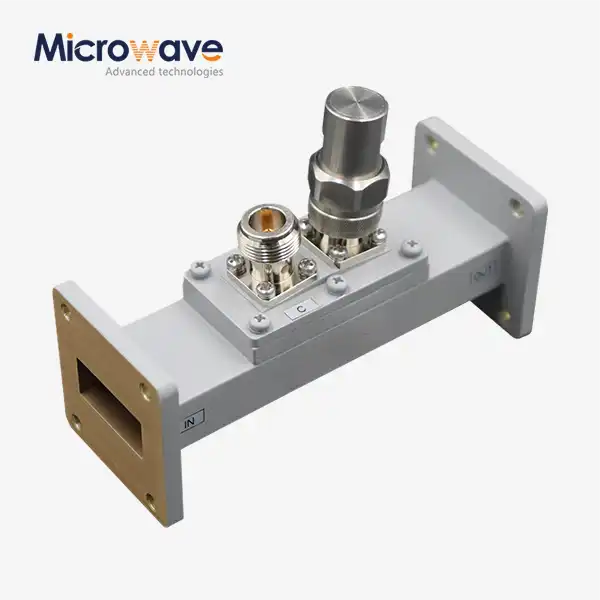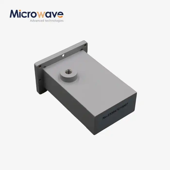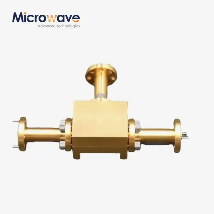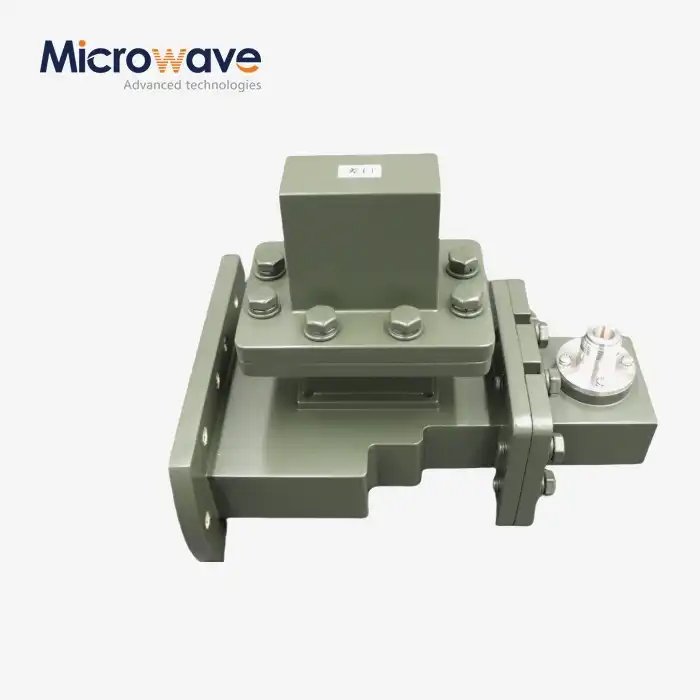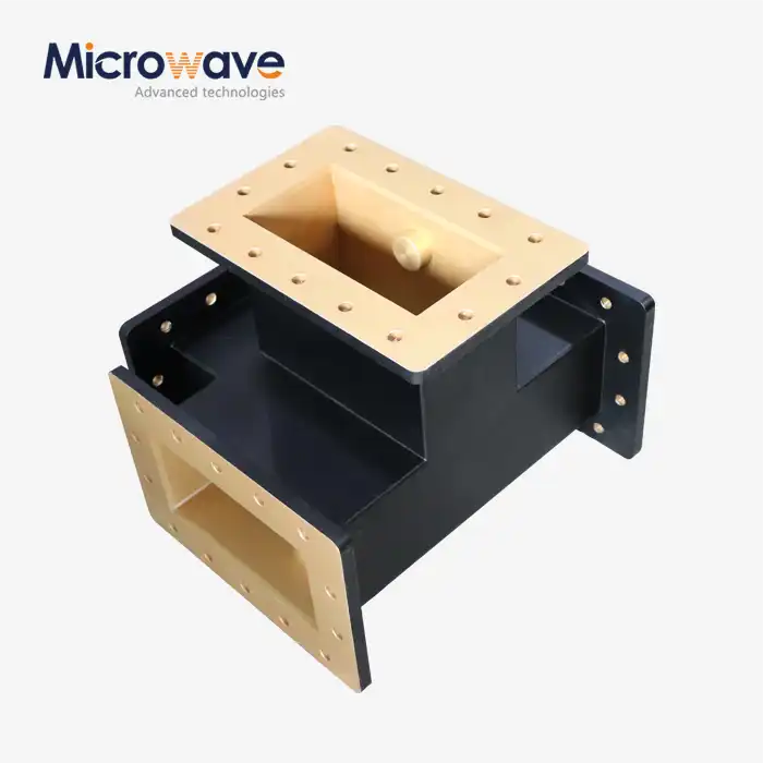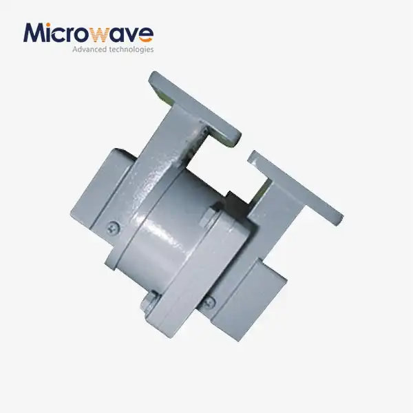

Waveguide Single Channel Rotary Joint
Waveguide Single Channel Rotary Joint — RF Rotary Coupler for Radar, Satellite & Defense Systems
Waveguide Single Channel Rotary Joint technology solves a core challenge in rotating antenna systems: maintaining continuous, low-loss microwave energy transfer across a 360° rotating interface. ADM's single-channel waveguide rotary joints propagate EM waves through a hollow metallic tube using TE11 or TM01 modes, keeping insertion loss below 0.2 dB and VSWR under 1.25:1. Available in I-Type, L-Type, and U-Type configurations, they cover L through Ka-band with high-end models reaching 40–50 GHz.
What Is a Waveguide Single Channel Rotary Joint?
A single-channel waveguide rotary joint — also referred to as a rotary coupler — enables high-frequency RF energy to cross a continuously rotating interface without restricting angular travel or causing cable fatigue.
Traditional twisted cables fail under continuous 360° rotation. A waveguide rotary joint eliminates that constraint by maintaining consistent impedance matching throughout full rotation, protecting high-power transmitters such as TWTs and klystrons from damaging signal reflections.
Three mechanical styles are available to match different system geometries:
· I-Type — Both arms are aligned with the rotation axis
· L-Type — One arm is perpendicular to the rotation axis
· U-Type — Both arms are perpendicular to the rotation axis

Key Technical Specifications
Parameter | Specification |
Frequency Range | L, S, C, X, Ku, Ka-bands (up to 40–50 GHz, custom) |
VSWR | ≤ 1.25:1 (premium models ≤ 1.15:1) |
Insertion Loss | < 0.2 dB |
WOW (Insertion Loss Variation during rotation) | ±0.05 dB |
Peak Power Handling | Megawatt class |
Average Power Handling | Kilowatt class |
Pressurization Support | 0.5–2.0 bar (dry air, N₂, or SF₆) |
Housing Material | Aluminum 6061-T6 or Copper/Brass |
Surface Treatment | Chromate conversion coating, silver or gold plating |
Bearing Grade | ABEC-7 precision ball bearings |
Sealing Rating | IP65 / IP67 |
Operational Lifespan | 5–10 million rotations |
Flange Standards | IEC / EIA (e.g., WR90/WG16), CPR-F/G/C |
Available Types | I-Type, L-Type, U-Type |
Material and Construction
The housing is made from either Copper/Brass (for better heat absorption) or Aluminium 6061-T6 (for high strength at low weight). Some surface finishes are chromate conversion coating, which protects against corrosion, and silver or gold plating, which makes the metal better at conducting electricity.
The inside shapes are made to spread out the electric field, which makes it less likely that the voltage will drop during high peak power waves. ABEC-7 precision bearings have low starting force and keep turning even over their full service life.
With double-barrier dynamic sealing, the joint is protected to IP65 or IP67, so it can be used in harsh environments like marine salt fog, desert dust, and more.
Application Scenarios
The Waveguide Single Channel Rotary Joint is used when an antenna for radar or transmission needs to keep turning while keeping the RF signal path clear.
Air Traffic Control (ATC) Radar
The joint sends out high-power pulses in either L-band or S-band all the time in ATC main surveillance radar. A choke design that doesn't touch anything is used to make it last longer and require less regular internal maintenance.
Radar for Marine Navigation and Fire Control
Parts of naval sites are exposed to salt fog and humidity. For these systems, the rotary joints have chromate conversion coatings and IP65/IP67 sealing to keep out water, which would cause arcing at the X-band frequencies needed for target tracking if it got in.
Satellite Communication on the Move (SOTM)
Mobile Ku and Ka-band satellite terminals, whether they are on a ship or a vehicle, need to keep their antennas tracked even when they move. The main path for the RF uplink is through the rotary joint. Because it is small and light, it lowers the inertia of stabilisation servo motors, and phase stability is important for keeping link quality.
Medical Linear Accelerators (Linac)
In systems for treating cancer, the joint sends high-power RF from a klystron to the accelerating waveguide on a gantry that spins. For accurate beam delivery, phase stability and low RF leakage are very important.
Military Surveillance Radar on the Ground
These joints work with continuous duty cycles and high torque loads. They are often pressurised with dry nitrogen or SF₆ to stop internal arcing during high-power S-band or L-band pulse transmission.
Hybrid Integration: RF + Power + Data
Only RF energy can pass through the waveguide path. When system designs need DC power, Ethernet, or serial data to go through the same rotating interface, ADM can make hybrid units with an electrical slip ring centred around the waveguide core. This lets RF and electrical data be sent at the same time in a small unit, which is often needed in radar pedestals and stabilised VSAT platforms.
Pressurization for High-Power Applications
When the highest power needs get close to the breaking point, SF₆ or dry nitrogen at 0.5 to 2.0 bar can be used to pressurise the internal space. This makes the medium inside the waveguide more dielectrically strong, which lowers the chance of arcing while pulses are being sent.
For megawatt-class radar transmitters, where short-term voltage spikes during pulse compression could cause internal breakdown, pressurisation is often required.
Testing and Quality Assurance
The Waveguide Single Channel Rotary Joint is tested in ADM's 24-meter Microwave Darkroom, which can measure from 0.5 GHz to 110 GHz, which is all the normal waveguide bands used in production. Before a product is shipped, it is tested for insertion loss, VSWR, WOW change, and power handling. The measurements of the flange are checked against IEC and EIA standards to make sure they will fit with your current waveguide system.
Customization Options
Custom configurations can be made for all the important factors, such as the waveguide band, the flange type (CPR-F, CPR-G, or CPR-C choke), the mechanical style (I/L/U-Type), the housing material, the surface treatment, the pressurisation port, and the slip ring integration.
When there are special needs when it comes to frequency, power, or the environment, ADM's tech team works directly with customers to come up with a configuration that works.
FAQ
Q: How does pressurisation keep high-power joints from arcing?
A: The shapes of the inside are made to spread out the electric field. Putting SF₆ or dry nitrogen pressure inside the cavity makes the dielectric stronger and lowers the chance of voltage breakdown during peak pulse transmission.
Q: What is WOW, and why does radar care about it?
A: WOW stands for "Variation of Insertion Loss". It shows how much insertion loss changes as the joint turns. When WOW is high, amplitude modulation is added at the antenna spinning frequency. On Doppler radars, this might show up as noise or a fake target. The goal of ADM is to keep WOW at a low level, within ±0.05 dB.
Q: Can power and data be sent through the waveguide joint as well?
A: The waveguide channel only sends RF energy. ADM makes hybrid assemblies with an electrical slip ring mounted concentrically around the waveguide center for uses that need DC power or data transmission as well.
Q: How do I pick between choke flange and CPR flange?
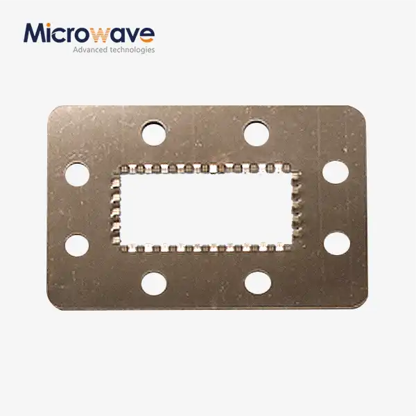
A: For flat cover flanges (CPR-F/G), the surfaces that fit together must be in good physical contact. Choke flanges (CPR-C) have a groove that stops RF leaking even if the contact isn't perfect. All of the rings meet IEC or EIA standards (for example, WR90/WG16) to make sure they can fit together properly.
Q: How long do you think it will last?
A: The normal working conditions say that it should last between 5 and 10 million rotations. Routine maintenance usually only includes checking the pressure levels and looking at the outside.
Q: What kinds of mechanical combinations are there?
A: There are three styles: I-Type, L-Type, and U-Type. I-Type has both arms in line with the turning axis, L-Type has one arm perpendicular, and U-Type has both arms perpendicular. In radar pedestals and antenna drive systems, each style works best with a different set of mechanical layouts.