What Are the Benefits of Using a Waveguide Cable?
When it comes to sending high-frequency signals in mission-critical RF and microwave systems, waveguide wire bundles are the best. Engineers can handle high-power signals at frequencies from 18 GHz to 110 GHz with little loss using these special transmission lines that combine the low-loss properties of hard waveguides with mechanical flexibility. Waveguide cable is the best choice for military radar systems, satellite ground stations, and precision test equipment that can't risk signal integrity because the core's overlapping, complex design keeps phase stability even when bent. Their strong design can handle high and low temperatures, vibrations, and weather stress, and they always work electrically in tough industrial settings.
Understanding Waveguide Cables: Key Features and Working Principles
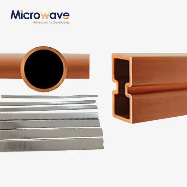
Waveguide cable kits are a middle ground between hard waveguide parts and the need for bendable links in complicated RF systems. In contrast to coaxial cables, which send signals in the TEM mode, these systems work in the TE or TM modes through a hollow conducting structure. They usually have a flexible connecting metal core that lets them bend and twist along the axis.
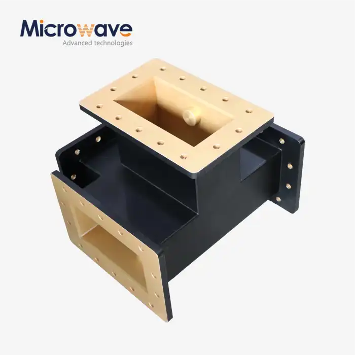
The basic structure is made up of precisely cut flanges that meet industry standards like CPR, UG, or UBR requirements. These are linked by a flexible core made from copper or brass strips that have been silver-plated. This design lets the mechanical parts move while keeping the electrical connections and protection solid. Whether it's made of neoprene for outdoor placements or polished metal for labs, the upper protective jacket protects against the environment without affecting the RF performance.
Rectangular and Circular Configurations
Most microwave uses use rectangular waveguide wares. Their frequency range is determined by their size, such as WR-90 for X-Band or WR-28 for Ka-Band. The accuracy of these parts' measurements has a direct effect on their resistance and cutoff frequency. Circular designs are better in some situations where polarization freedom is needed or where room is limited, but they aren't used as much in normal industrial settings.
Material Selection Impact
Both electrical and mechanical efficiency are greatly affected by the core material and covering that are used. Silver finishing lowers the resistance of the surface, which lowers insertion loss, especially at higher frequencies. For flying uses, aluminum construction is lighter, while copper construction is better for ground-based systems because it conducts electricity more efficiently. In aircraft uses, the safety clothing material needs to be flexible, resistant to the environment, and able to work in temperatures ranging from -55°C to 125°C.
Operational Principles
Electromagnetic waves move through the empty structure by bouncing off of the electrical walls. The shape of the structure determines the modes that can exist at different frequencies. At microwave frequencies, this way of transmission naturally has less absorption than coaxial options. The insertion loss is usually between 0.3 and 0.5 dB per meter, but it depends on the frequency and waveguide size. Since there is no middle wire, there are no dielectric losses, which are a problem with coaxial systems at high frequencies.

Core Benefits of Using Waveguide Cables in Industrial Applications
Waveguide wire bundles are used in defense and industrial settings because they have many strong technical and practical benefits that directly solve the problems procurement engineers face when they have to describe high-frequency transmission systems.
Superior Signal Integrity and Low Attenuation
Waveguide systems have about a tenth of the insertion loss of quality coaxial lines at frequencies above 18 GHz. This huge drop in signal loss means longer transmission lengths without amplification, lower system noise levels, and better link budgets overall. This efficiency directly improves the uplink power efficiency and downlink sensitivity in satellite ground stations that handle Ka-band communications. This makes it possible for more operations to be made when the weather is bad.
VSWR stays below 1.25:1 across the working band because of the controlled impedance environment inside a properly ended waveguide cable and waveguide unit. At this level of impedance matching, echoes are kept to a minimum. If they happened more often, they would lower the quality of the signal, cause crosstalk, and maybe even hurt high-power receivers. When the Vector Network Analyzer is being made, these factors are checked across the whole frequency range, and test data plots are shown as proof of quality.
Exceptional Power Handling Capability
Waveguide systems can handle peak and average power levels a thousand times higher than coaxial wires, which break down at high power levels due to heat. This feature is very important in radar emitters, high-power amplifier links, and industrial heating situations where kilowatts of RF power need to be sent without any problems or safety issues. The big cross-sectional area spreads out heat energy, which stops spikes that lower the performance of coaxial cables.
Phase Stability Under Mechanical Stress
When the premium waveguide cable assemblies are bent around their minimum bend radius, the phase variation stays within ±2 to 5 degrees. Because they are stable, they can be used in phased array radars, where the antenna elements need to keep exact phase relationships, and in test systems, where accuracy of measurements relies on electrical length being stable. This performance is checked by bending parts around mandrels during quality control while keeping an eye on phase characteristics.
Environmental Resilience
The strong mechanical design can handle rough situations that would damage other transfer ways. Outdoor systems can handle changes in temperature, exposure to wetness, UV rays, and physical shaking without losing their electrical integrity. Assemblies for military use often have to be able to handle damp, salt fog, and tests at very high and very low temperatures while still working properly electrically. Pressure tests with nitrogen or dry air confirm that pneumatic sealing works in outdoor or pressurized waveguide systems, keeping wetness out that would change the dielectric properties.
Reduced Maintenance Requirements
The lack of internal insulating materials that break down over time, along with the mechanical strength of the connecting core, makes for a longer service life with little upkeep. Installations in radar sites and satellite earth stations usually don't need to be replaced for decades. This lowers the costs over their whole life and keeps the system running as much as possible. This dependability is especially helpful in remote sites where getting service access costs a lot and causes operations to stop.
Waveguide Cables vs. Alternative Transmission Solutions: A Comparative Perspective
Selecting optimal transmission technology requires understanding how waveguide assemblies compare against alternatives across multiple performance dimensions relevant to procurement decisions.
Coaxial cables remain the default choice for many RF applications due to lower initial costs and familiar installation practices. At frequencies below 10 GHz, their performance often satisfies system requirements with acceptable loss budgets. However, as frequency increases into millimeter-wave bands, coaxial insertion loss escalates rapidly while power handling diminishes. A 40 GHz system using premium coaxial cable might experience 3-4 dB per meter loss compared to 0.4 dB per meter for an equivalent waveguide assembly—a difference that compounds over transmission distances and severely impacts link budgets.
Fiber optic systems excel at transmitting digital data over long distances but cannot directly handle RF signals without conversion. Applications requiring analog signal transmission, high power levels, or operation in strong electromagnetic environments favor waveguide solutions. The direct RF transmission path eliminates conversion losses and complexity while maintaining signal phase information critical for radar and phased array applications.
Cost-Performance Trade-offs
Waveguide cable and waveguide assemblies command higher unit costs than coaxial alternatives, reflecting the precision manufacturing, quality control, and specialized materials involved. Procurement teams must evaluate this initial investment against lifecycle performance factors: reduced signal loss enabling smaller amplifiers, extended operational life minimizing replacement frequency, and superior reliability reducing maintenance costs. In high-value systems where performance directly impacts mission success—military radar, satellite communications, and 5G backhaul infrastructure—the total cost of ownership calculation consistently favors waveguide technology despite higher acquisition costs.
Installation and Integration Considerations
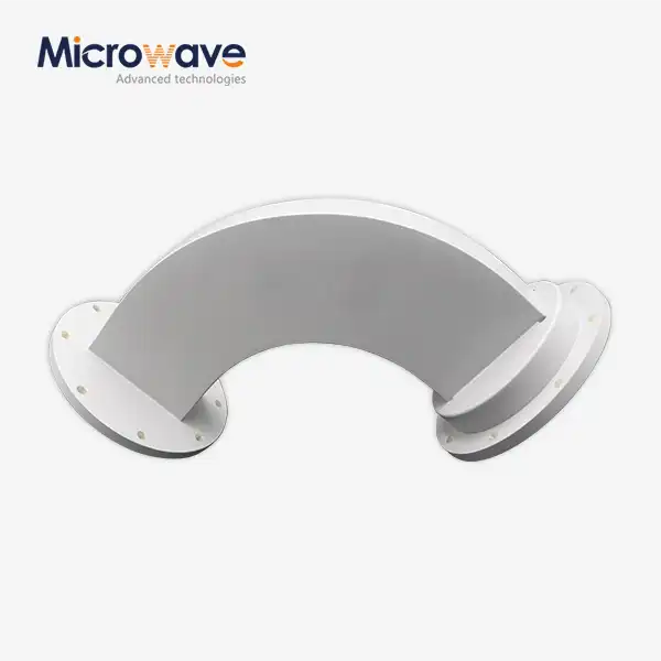
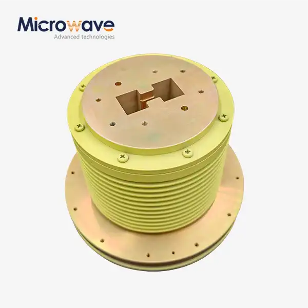
The flexibility of waveguide cable assemblies addresses a practical challenge that rigid waveguide sections create: accommodating dimensional tolerances, thermal expansion, and vibration in system installations. Flexible sections absorb misalignment between components mounted on separate structures, eliminating the need for complex custom plumbing. The minimum bend radius specification—typically around 65mm for WR-75 assemblies—must be respected to prevent permanent deformation of the interlocking core that would cause VSWR degradation.
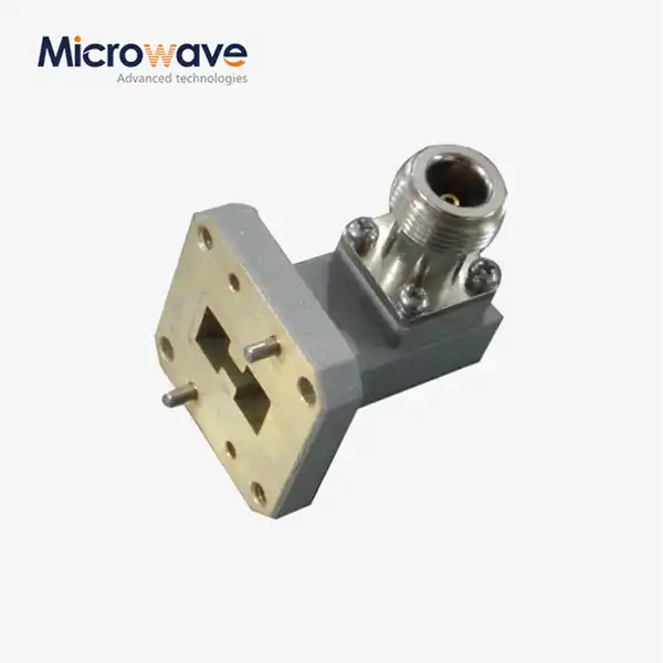
Flange compatibility represents a critical procurement specification. Mismatched flange types lead to RF leakage, impedance discontinuities, and potential arcing at high power levels. Procurement specifications must precisely identify flange standards (UG-covers, PBR, UBR, and CBR designations) to ensure proper mating with existing system components. GO/NO-GO gauges verify bolt hole alignment and interface compatibility during receiving inspection.
Procurement and Sourcing: How to Buy Quality Waveguide Cable?
Sourcing waveguide cable assemblies that meet demanding technical requirements while optimizing procurement efficiency requires attention to supplier qualifications, specification details, and quality verification processes.
Supplier Qualification Criteria
Reputable manufacturers demonstrate their capabilities through certifications that indicate commitment to quality management and process control. ISO 9001 certification verifies that documented quality systems govern manufacturing processes, while RoHS compliance confirms restriction of hazardous substances meeting environmental regulations. Military and aerospace suppliers often hold additional certifications enabling them to meet defense specifications.

Manufacturing capabilities matter significantly for waveguide assemblies. Suppliers equipped with advanced microwave measurement systems—Vector Network Analyzers covering the full operating frequency range, precision flange inspection equipment, and environmental test chambers—can verify performance through actual measurement rather than relying solely on design calculations. At Advanced Microwave Technologies Co., Ltd., our laboratories feature measurement capabilities extending to 110 GHz, enabling full characterization of millimeter-wave assemblies that push frequency boundaries.
Critical Specification Parameters
Procurement documents must clearly define electrical and mechanical requirements to ensure delivered assemblies meet system needs:
- Frequency Range: Specify both the nominal operating band and any guard bands required for filter transitions or frequency agility. The waveguide size must support propagation at the lowest operating frequency while avoiding higher-order modes at the upper frequency limit.
- Electrical Performance: Define maximum acceptable insertion loss, minimum return loss (or maximum VSWR), and phase stability requirements if applicable. Specify whether these parameters apply under static conditions only or must be maintained during flexure.
- Mechanical Configuration: Document flange types for both ends (they need not be identical), overall length, and any bend radius constraints imposed by installation geometry. Specify whether twistable construction is required for applications needing rotational freedom.
Environmental Requirements: Identify operating temperature range, humidity exposure, and any specific environmental tests (salt fog, vibration, thermal cycling) that must be passed before acceptance.
Volume Pricing and Supply Chain Management
Waveguide assemblies often involve significant per-unit costs due to precision manufacturing and quality verification. Volume commitments enable suppliers to optimize production runs, reducing per-unit costs through manufacturing efficiency. Procurement teams managing multi-year projects or standardized system architectures should explore framework agreements that secure pricing while maintaining flexibility for delivery scheduling.
Lead times vary based on configuration complexity and current production loading. Standard configurations using common flange types, waveguide cable, and waveguide sizes typically ship within weeks, while custom assemblies requiring unique dimensions or special materials may require extended manufacturing schedules. Early supplier engagement during system design phases allows manufacturing considerations to inform design decisions, avoiding specifications that unnecessarily complicate production or extend delivery timelines.
Conclusion
Waveguide cable assemblies represent the optimal transmission solution for high-frequency systems where signal integrity, power handling, and reliability justify their engineering sophistication and associated costs. Their fundamental advantages—exceptionally low insertion loss, superior power capacity, mechanical flexibility, and environmental resilience—address critical technical challenges in satellite communications, radar systems, and precision test equipment.
Procurement decisions should evaluate these assemblies within the context of total system performance and lifecycle costs rather than focusing narrowly on initial acquisition expense. The specification process must carefully define electrical, mechanical, and environmental requirements while ensuring supplier capabilities align with quality and delivery expectations. As microwave and millimeter-wave systems continue advancing into higher frequency bands for 5G infrastructure, satellite networks, and defense applications, waveguide technology remains indispensable for achieving the performance these systems demand.
FAQ
1. What frequency ranges can waveguide cables effectively support?
Waveguide cable assemblies operate across the microwave and millimeter-wave spectrum, typically from 18 GHz extending beyond 110 GHz, depending on the waveguide size. Each waveguide designation (WR-90, WR-28, etc.) supports a specific frequency band determined by its cross-sectional dimensions. The cutoff frequency represents the lower operational limit, while the upper frequency is constrained by higher-order mode propagation that degrades performance.
2. Can these assemblies withstand outdoor environmental conditions?
Properly specified waveguide assemblies excel in outdoor installations. Weather-resistant jacketing materials like neoprene or silicone protect the flexible core from moisture, UV radiation, and temperature extremes. Pressurized designs include pneumatic sealing verified through pressure testing with nitrogen, preventing moisture ingress that would alter electrical properties. Assemblies meeting military environmental specifications survive humidity, salt fog, and thermal cycling tests that simulate years of outdoor exposure.
3. How do I choose between waveguide and coaxial cable for my application?
The decision depends primarily on frequency and performance requirements. Above 18 GHz, waveguide assemblies provide dramatically lower insertion loss and higher power handling, justifying their higher cost in performance-critical applications. Coaxial cables remain viable for lower frequencies, shorter distances, or budget-constrained applications where their performance limitations prove acceptable. Consider total system performance, including amplifier requirements, link budgets, and reliability needs, rather than cable cost alone.
Partner with ADM for Your Waveguide Cable Requirements
Advanced Microwave Technologies Co., Ltd. stands ready to support your high-frequency transmission needs with over two decades of engineering excellence in waveguide cable manufacturing. Our ISO 9001-certified production facilities, equipped with measurement capabilities extending to 110 GHz, deliver assemblies that meet the most demanding specifications for aerospace, defense, and telecommunications applications. Whether you require standard configurations for rapid deployment or custom-engineered solutions addressing unique system constraints, our technical team collaborates closely with procurement and engineering professionals to optimize performance and value.
We understand that B2B procurement decisions involve evaluating multiple waveguide cable suppliers based on technical capability, quality systems, and supply chain reliability. Our comprehensive OEM services include rapid prototyping, extensive technical documentation, and responsive support throughout your product lifecycle. Contact our team at craig@admicrowave.com to discuss your specific requirements, request technical specifications, or obtain quotations for volume requirements. Experience the difference that precision engineering and rigorous quality control deliver in every waveguide cable assembly we manufacture.
References
1. Pozar, David M. Microwave Engineering, 4th Edition. Wiley, 2011.
2. Collin, Robert E. Foundations for Microwave Engineering, 2nd Edition. IEEE Press, 2001.
3. Chatterjee, Ramo. Microwave and RF Engineering. CRC Press, 2018.
4. Institute of Electrical and Electronics Engineers. IEEE Standard for Rectangular Waveguides (IEEE Std 1785-2016).
5. Military Standard. Waveguides and Waveguide Flanges, General Requirements for (MIL-DTL-3922).
6. Saad, Theodore S. Microwave Engineers' Handbook, Volume 2. Artech House, 1971.