


WG Probe Coupler Installation Best Practices
The best way to install a WG Probe Coupler is to follow a set of steps that make sure the signal stays intact and the system works well for a long time. To properly install these precise electromagnetic transition components, you need to pay close attention to how they fit together mechanically, how well they match resistance, and how the environment affects them. For a WG probe coupler to be installed correctly, it needs to be checked thoroughly before it is put in place and then tested thoroughly afterward using methods that check performance levels across specific frequency ranges.
Understanding WG Probe Couplers – Fundamentals and Key Specifications
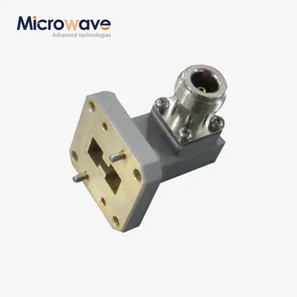
In the world of electromagnetics, WG probe couplers are very important because they connect coaxial communication lines to waveguide systems. These carefully designed parts use a metal probe element placed in the waveguide cavity in a way that makes it easy for energy to move between different transmission modes. The probe is carefully placed at the right distances from the waveguide's short-circuit wall so that it works as a quarter-wave monopole antenna and sends signals forward as much as possible through positive interference.
Core Applications and Industry Implementation
Because they are so flexible, probe couplers are used in many high-stakes businesses where signal integrity is very important. Within the aerospace industry, these parts make radar and navigation systems that need to work perfectly in harsh situations possible. Defence companies use probe couplers in mission-critical communication systems that need to be very reliable and consistent in how they work. These devices make sure that signals don't get lost between ground station equipment and antenna feeds. They are used by satellite communication networks to support everything from TV broadcasts to the internet's core infrastructure. Another important area where probe couplers are used is in telecommunications infrastructure, where they make it easier for standard-impedance solid-state electronics to connect to high-frequency waveguide distribution networks. Research labs and industrial labs use these parts to make precise measurement systems that need to be very good at linking and have very little signal distortion.

Essential Technical Specifications
Understanding key performance factors helps you make smart choices during the buying and installation process. Insertion loss for well-designed couplers is usually between 0.1 and 0.5 dB, which has a direct effect on how well the whole system works. The coupling factor specifies how much signal power is extracted or injected. Typical values range from -10 dB to -30 dB, but they can be higher or lower based on the application. Directivity performance, which is often higher than 20 dB in high-quality devices, keeps signal tracking accurate by reducing unwanted reflections. Power handling varies a lot depending on the materials used to build the unit, customized OEM waveguide couplers, and how it is cooled. High-performance units can handle continuous wave action at several hundred watts. Specifications for the frequency range must match the needs of the system, since the size and placement of the probe have a big impact on how well it works in different microwave bands. Voltage Standing Wave Ratio (VSWR) numbers, which should be less than 1.2:1, show how well the impedance matching works between the coaxial and waveguide connections.
Pre-Installation Checklist – Preparing for Optimal WG Probe Coupler Setup
Thorough preparation significantly reduces installation complications and ensures optimal performance from the outset. The pre-installation phase requires systematic verification of compatibility factors that influence both mechanical fit and electrical performance. Environmental considerations play an equally important role in determining long-term reliability and operational stability.
Compatibility Verification Procedures
Verification of dimensional compatibility is the first step in a good installation. Different types of waveguide flanges must have the same bolt designs, gasket grooves, and pressure plate configurations. Standard flanges like WR-90, WR-75, and WR-62 all need different mounting tools and ways to be lined up. Frequency band compatibility is more than just operating ranges; it also takes into account where the probe is placed in relation to factors that change with wavelength. Specifications for coaxial connectors need to be carefully read to make sure they work with current equipment. Standard 50-ohm systems usually use SMA, N-type, or precision connectors, based on the power level and frequency needs. Depending on how the system is set up and how fast it runs, impedance-matching networks may need to be adjusted. When you look over the documentation, you should look at the manufacturer's specs, installation plans, and the torque values that are suggested for all mechanical connections.
Environmental and Handling Considerations
Temperature cycling can have a big effect on long-term dependability, especially in aerospace or outdoor systems. Different materials may have different thermal expansion factors, which can cause mechanical stress at interface points. This stress could eventually hurt electrical performance. During installation, controlling humidity is very important to keep condensation from forming inside waveguide sections, which can lead to rusting and signal loss. Protocols for controlling contamination keep dust, wetness, and other things that hurt performance from getting on sensitive surfaces. Even though they aren't always necessary, clean room processes offer extra safety for installations that need to be very precise. When you handle things the right way, you can keep probe elements and connector contacts from getting damaged. These are usually the most fragile parts during installation.
Step-by-Step Installation Procedures for WG Probe Couplers
Mechanical installation begins with careful positioning of the coupler assembly within the waveguide system. Proper torque application prevents over-tightening that can distort flange surfaces while ensuring adequate sealing pressure for electromagnetic containment. Sequential tightening patterns distribute clamping forces evenly across flange interfaces, preventing warpage that creates signal leakage paths.
Mechanical Alignment and Positioning
Precision alignment tools facilitate accurate positioning of probe elements relative to waveguide boundaries and electromagnetic field distributions. Digital calipers and precision gauges verify critical dimensions during installation, ensuring compliance with manufacturer specifications. Gasket installation requires attention to proper customized OEM waveguide couplers seating and compression to maintain both environmental sealing and electrical continuity. The probe penetration depth critically affects the coupling coefficient and impedance matching characteristics. Adjustment mechanisms, when present, allow fine-tuning of electrical performance after mechanical installation completion. Locking mechanisms prevent inadvertent movement during system operation while maintaining adjustment accessibility for future optimization.
Electrical Connection and Testing Protocols
Coaxial connections demand careful attention to center conductor alignment and dielectric integrity. Connector torque specifications prevent damage to precision threads while ensuring reliable electrical contact. Cable routing should minimize mechanical stress on connector interfaces and provide adequate service loops for maintenance access. Post-installation verification procedures validate both mechanical integrity and electrical performance. Return loss measurements confirm proper impedance matching across operating frequency ranges. Insertion loss testing verifies acceptable signal transmission characteristics. Coupling factor measurements ensure compliance with design specifications and system requirements. Network analyzer measurements provide a comprehensive characterization of installed performance. Swept frequency testing reveals resonances or anomalies that may indicate installation issues. Time domain reflectometry can identify specific locations of impedance discontinuities when troubleshooting becomes necessary.
Performance Optimization and Maintenance Tips
Long-term performance optimization requires systematic attention to factors that influence signal integrity and coupling accuracy over extended operational periods. Environmental effects, mechanical settling, and component aging all contribute to gradual performance changes that may require periodic adjustment or maintenance intervention.
Signal Integrity Enhancement Strategies
Monitoring performance on a regular basis sets baselines that make it possible to spot trends of decline early on. Key parameters like insertion loss and return loss can be tracked by automated monitoring systems, which can send alerts when numbers go above certain limits. Trend analysis helps tell the difference between effects of ageing that are normal and serious problems that need instant attention. Temperature compensation methods take into account how temperature changes affect the placement of probes and the matching of impedance. For some installations, materials that don't change much in temperature or active compensation systems that keep working at a wide range of temperatures are helpful. Vibration isolation keeps mechanical noises from messing up the precise placement of probes in places with a lot of vibration.

Preventive Maintenance Protocols
Customised inspection schedules for each operational setting help find problems before they affect the system's performance. Visual checks show any rust, contamination, or mechanical damage that might affect how well something works. When you examine a connector, you should look at the thread condition, the integrity of the center conductor, and the dielectric wear patterns. Cleaning methods use the right chemicals and methods to get rid of dirt and grime without hurting delicate surfaces. Ultrasonic cleaning might be good for precision connectors, but most waveguide connections only need to be cleaned by hand. When you dry things the right way, you keep the wetness out, which can stop corrosion or dielectric breakdown. When performance testing is needed, calibration checking makes sure that measurements are correct. Calibration artefacts and reference standards make measurements more accurate by providing a way to track them back to their original sources. Keeping records of maintenance tasks helps quality assurance programs and meets legal standards for compliance.
Selecting the Right WG Probe Coupler Supplier
Supplier selection significantly impacts both immediate procurement success and long-term operational satisfaction. Established manufacturers like Keysight, Anritsu, and Rohde & Schwarz offer comprehensive product lines backed by extensive engineering support and global service networks. Specialized suppliers such as Narda and Mini-Circuits provide focused expertise in specific frequency ranges or application areas.
Technical capability assessment should examine manufacturing tolerances, test procedures, and quality certifications relevant to specific applications. ISO 9001 certification indicates systematic quality WG Probe Coupler management practices, while AS9100 certification demonstrates aerospace industry compliance. Military specifications (MIL-STD) compliance may be required for defense applications. Advanced Microwave Technologies Co., Ltd brings over two decades of specialized experience in precision microwave components, including custom WG probe coupler solutions tailored to specific application requirements. Our ISO 9001:2015 certified manufacturing processes and RoHS compliant components ensure consistent quality and regulatory compliance across all product lines. The company's 24-meter microwave darkroom facility enables comprehensive testing and validation across frequency ranges up to 110 GHz, providing customers with verified performance data and customization capabilities that larger suppliers often cannot match. Lead time considerations become particularly important for prototype development or urgent replacement requirements. Standard catalog items typically ship within days, while custom configurations may require several weeks for design and manufacturing. Emergency support capabilities and expedited delivery options provide additional value during critical situations. Cost evaluation should consider total ownership costs rather than simple unit pricing. Higher-quality components often provide superior long-term reliability and performance stability, reducing maintenance costs and system downtime. Volume pricing structures and long-term supply agreements can provide significant cost advantages for recurring requirements.
Conclusion
Successful WG probe coupler installation requires systematic attention to mechanical precision, electrical optimization, and long-term maintenance considerations. Proper preparation, careful execution of installation procedures, and ongoing performance monitoring ensure reliable operation across diverse applications. The selection of qualified suppliers and adherence to industry best practices minimize risks while maximizing system performance and operational longevity.
FAQ
1. What factors determine proper WG probe coupler positioning?
Probe positioning depends on operating frequency, desired coupling coefficient, and waveguide dimensions. The probe typically requires positioning at specific distances from the waveguide walls and short-circuit terminations to achieve optimal electromagnetic field coupling. Wavelength-dependent spacing ensures constructive interference and maximum energy transfer efficiency.
2. How can installation errors affect system performance?
Installation errors such as improper torque application, contaminated interfaces, or misaligned components can significantly degrade electrical performance. Poor mechanical connections create signal reflections and increase insertion loss, while contamination can cause power handling limitations and long-term reliability issues.
3. What maintenance intervals are recommended for WG probe couplers?
Maintenance intervals vary based on environmental conditions and application requirements. Typical recommendations include quarterly visual inspections, annual performance verification testing, and immediate attention following exposure to extreme conditions. Critical applications may require more frequent monitoring to ensure continuous, reliable operation.
Partner with ADM for Your WG Probe Coupler Requirements
Advanced Microwave Technologies Co., Ltd stands ready to support your precision microwave component needs with comprehensive WG probe coupler solutions backed by decades of engineering expertise. Our team provides technical consultation, custom design services, and ongoing support to ensure optimal performance in your specific applications. Whether you require standard catalog items or specialized configurations for unique requirements, ADM delivers quality solutions with competitive pricing and reliable delivery schedules. Contact our engineering team at craig@admicrowave.com to discuss your WG probe coupler supplier requirements and discover how our expertise can enhance your project success.
References
1. IEEE Standard for Waveguide Components - Specification and Test Methods for Passive Waveguide Components, IEEE Std 149-1979.
2. "Microwave Engineering Handbook: Waveguide Components and Systems" by K.F. Warnick, Institute of Electrical Engineers, 2018.
3. "RF and Microwave Coupling Systems: Design and Installation Practices" by R.J. Cameron, Artech House Publishers, 2017.
4. "Waveguide Handbook: Theory and Applications in Modern RF Systems" by N. Marcuvitz, McGraw-Hill Professional Engineering, 2019.
5. "Precision Microwave Measurements: Calibration and Verification Procedures" by J.P. Dunsmore, Cambridge University Press, 2020.
6. "High-Frequency Electronic Systems: Installation and Maintenance Guidelines" by S.A. Maas, IEEE Press Series on Microwave Technology, 2016.
YOU MAY LIKE
 VIEW MORERight Angle Double Ridged WG To Coaxial Adapter
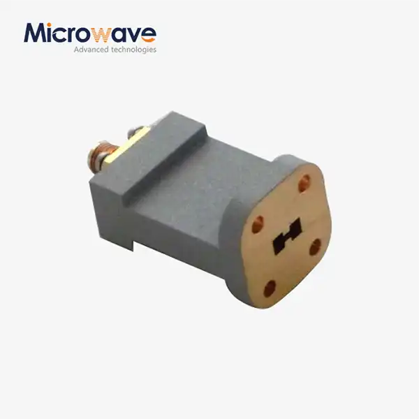 VIEW MOREEnd Launch Double Ridged WG To Coaxial Adapter
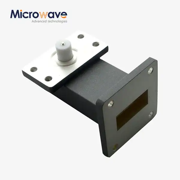 VIEW MORERight Angle Waveguide to Microstrip Adapter
 VIEW MOREWG Termination
 VIEW MOREDouble Ridge Waveguide Termination
 VIEW MOREWaveguide Power Divider
 VIEW MOREE-Plane Tee
 VIEW MORECrossguide Directional Coupler
