





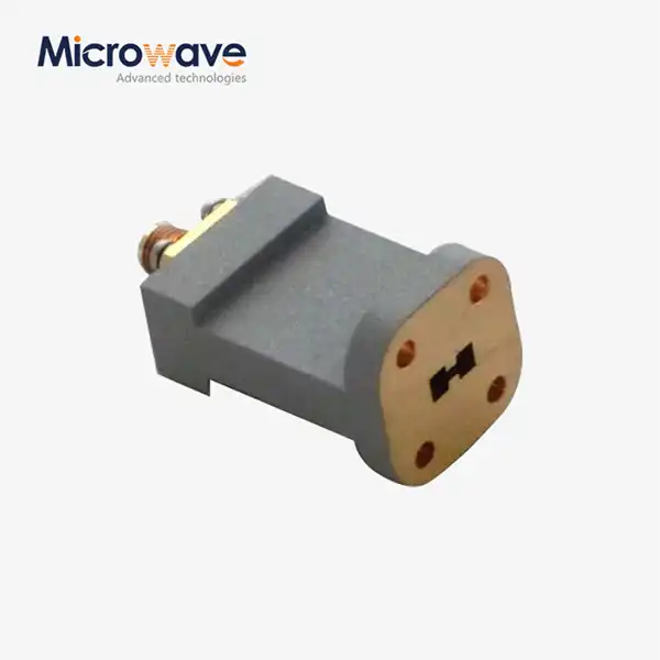
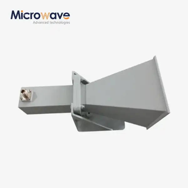
End Launch Double Ridged WG To Coaxial Adapter
End Launch Double Ridged WG To Coaxial Adapter — Broadband Transition for Wideband Microwave Systems
The End Launch Double Ridged WG To Coaxial Adapter from Advanced Microwave (ADM) provides a direct coaxial-to-waveguide transition across the full frequency range of double ridge waveguides — including configurations such as 2–18 GHz on WRD180. The internal ridge geometry lowers the cut-off frequency to support bandwidth ratios of 2.4:1 or 3.6:1 within a single unit. Standard models are non-pressure-sealed and rated at one atmosphere. Multiple flange types and coaxial connector options are available.
What Is an End Launch Double Ridged WG To Coaxial Adapter?
This component transitions signals between a 50-ohm coaxial line (TEM mode) and a double-ridged waveguide structure (TE10 mode). The double-ridged geometry uses two internal ridges to lower the cut-off frequency, which extends the usable bandwidth well beyond what a standard rectangular waveguide of the same aperture would support — allowing one adapter to span multiple octaves.
The "end launch" configuration positions the coaxial connector axially along the waveguide's propagation direction, typically mounted at the backshort plate. This keeps the cable path inline with the waveguide axis, which suits assemblies where a right-angle bend would create a physical obstruction or routing conflict.
The ridge structure also reduces the waveguide's characteristic impedance toward the 50-ohm coaxial standard, which narrows the impedance step at the transition and limits reflections across the operating band.


Key Technical Specifications
Parameter | Specification |
Frequency Coverage | Full range for double ridge waveguides (e.g., 2–18 GHz, WRD180) |
Bandwidth Ratio | 2.4:1 or 3.6:1 |
VSWR | < 1.5:1 across full band |
Impedance | 50 Ohm (coaxial interface) |
Connector Options | SMA, N-Type, TNC, 2.92 mm |
Body Material | Aluminum 6061-T6 or copper alloys |
Surface Finish | Chromate Conversion (MIL-C-5541), silver plating, or gold plating |
Operating Temperature | −55°C to +85°C |
Pressure Sealing | Non-pressure-sealed (standard models) |
Power Rating | Rated at one atmosphere |
Flange Types | Multiple configurations available |
Materials and Construction
The body of the End Launch Double Ridged WG To Coaxial Adapter is made from either aluminium 6061-T6 or copper alloys, depending on the application's weight and conductivity needs. You can treat the surface with Chromate Conversion Coating (MIL-C-5541), silver plating, or gold plating, depending on the electrical and environmental needs of the place where it will be used.
The most important mechanical property in this adapter is the ridge gap. It sets the cut-off frequency and the impedance curve for the whole band. Coordinate Measuring Machines (CMM) are used during production to make sure that the ADM machines can hold this dimension to within ±0.01 mm.
Every unit's coaxial pin depth and concentricity are controlled to meet MIL-STD-348 interface standards. This keeps mating connections from getting damaged when it's being put together and taken apart in the field.
Performance Characteristics
The ridge shape focuses the field in the gap area, which makes the waveguide's characteristic resistance closer to the 50-ohm coaxial standard. This lowers the reflection at the changeover and keeps the insertion loss the same across the given band.
Operating temperatures between -55°C and +85°C are enough to cover most defence assets in space and on the ground. The phase reaction stays the same across this range, which is important for systems that need signal paths between channels that work together.
In small integration areas, the end-launch profile keeps the adapter and cable coaxially aligned. This keeps the routing from bending, which would happen with a right-angle configuration.
Application Scenarios
Airborne Electronic Warfare and ECM Systems
EW and ECM platforms need wideband signal paths that stay open across a wide range of threat frequencies. The end-launch shape keeps the adapter parallel to the waveguide axis. This lets it fit into the small cable channels that are common in airborne fuselage assemblies, where a right-angle adapter would get in the way of routing.
Measurement of Broadband Antenna Patterns
When engineers connect these adapters to double-ridged horn antennas at test ranges, they can sweep across large frequency ranges, like 6 to 18 GHz, without having to switch hardware between sub-bands. So, there are fewer steps needed to re-calibrate, and the test output stays the same over long measurement runs.
Places to Test EMI/EMC
The adapter links wideband signal sources to broadband loads or antennas in electromagnetic compatibility labs. The two-ridged waveguide section can handle more power than a coaxial connection with the same bandwidth. It also keeps the frequency coverage needed to test across multiple regulatory frequency bands in a single sweep.
Quality Control Process
Before being sent out, each product is checked on its own. A Vector Network Analyser (VNA) sweep looks at VSWR and insertion loss over the whole band that was given. Any resonance spike leads to rejection, which could be caused by a mistake in the ridge gap or a connector pin that isn't sitting properly.
The CMM checks the ridge gap sizes to within ±0.01 mm. Every unit is checked against MIL-STD-348 to see how deep the connector pins go. For military orders, units go through Environmental Stress Screening (ESS), which checks that the coax-to-ridge transition stays mechanically and electrically intact. This testing includes temperature cycling and vibrations.
Configuration Options
ADM manufactures the End Launch Double Ridged WG To Coaxial Adapter in a range of configurations. Available variables include:
· Flange type: Multiple flange configurations matched to specific WRD numbers (e.g., WRD750)
· Coaxial connector: SMA, N-Type, TNC, or 2.92 mm
· Surface finish: Chromate conversion (MIL-C-5541), silver plating, or gold plating
· Body material: Aluminum 6061-T6 or copper alloys
Custom configurations are handled through ADM's engineering team. To initiate a custom build, contact ADM with your WRD number, required connector interface, operating frequency range, and any surface finish or environmental requirements.
FAQ
Q: If you compare this adapter to a regular rectangular waveguide adapter, how does it handle power?
A: Because the ridges are shaped in a way that focuses the electric field in a smaller cross-sectional gap, double-ridged waveguides can handle less average power than standard rectangular waveguides. The coaxial connection is usually the limiting part inside the adapter. N-Type or TNC connectors are usually better than SMA connectors for uses that need more power.
Q: What if I want to connect a WRD flange to a standard WR rectangular waveguide flange?
A: Not really. Between the WRD and WR models, the flange bolt patterns and internal shapes are different. To keep the signal strong and stop leakage at the joint, double-ridged flanges must be matched to the right WRD number. For example, a WRD750 flange can only fit with other WRD750 flanges.
Q: What are the most common reasons why these adapters have high insertion loss?
A: The three most common reasons are a surface finish inside the waveguide that is rough or doesn't conduct electricity well, the coaxial center conductor and the ridge at the transition not being lined up correctly, and the connector pin not being seated properly. All three are taken care of by ADM through machining tolerances, plating choices, and 100% VNA testing before shipping.
Q: Why would you use end launch instead of right-angle (top launch)?
A: End launch keeps the waveguide and coaxial cable on the same axis, which works well for assembly lines and small areas. A right-angle design adds a 90-degree bend that might not work with nearby parts in dense feed networks or airborne hardware layouts.
Q: What kinds of bandwidth rates are there?
A: 2.4:1 or 3.6:1 bandwidth ratios can be used with standard configurations. One example is the WRD650, which works from 6.5 to 18 GHz and includes the C, X, and Ku bands all in one adapter.
Contact Us
For technical questions or to discuss a custom configuration for the End Launch Double Ridged WG To Coaxial Adapter, contact ADM directly at craig@admicrowave.com.
YOU MAY LIKE
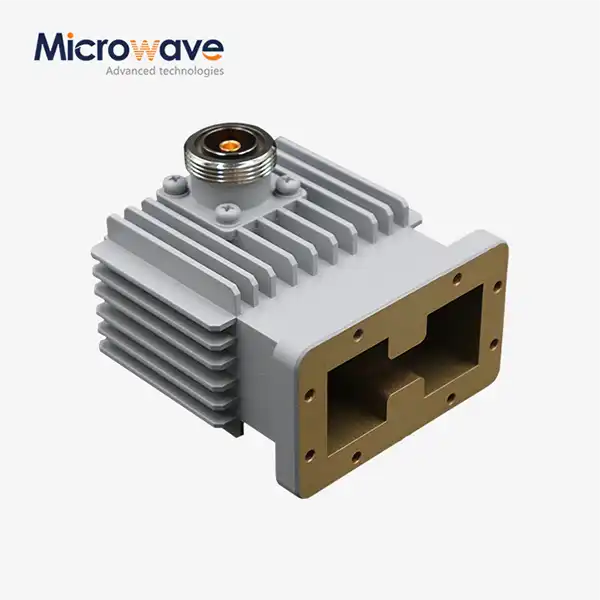 VIEW MOREHigh Power Waveguide to Coaxial Adapter
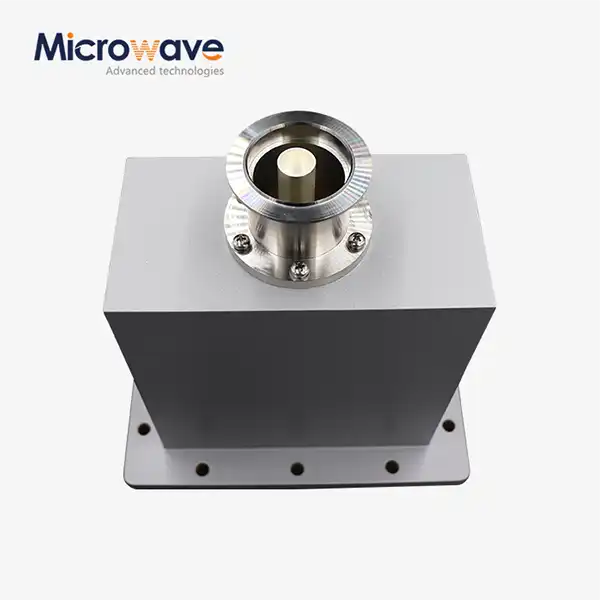 VIEW MOREEnd Launch Waveguide to Coaxial Adapter
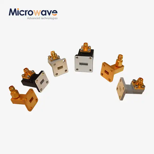 VIEW MORERight Angle Waveguide To Coaxial Adapter
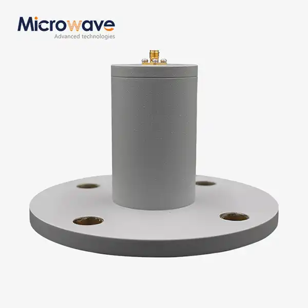 VIEW MORECircular Waveguide To Coaxial Adapter
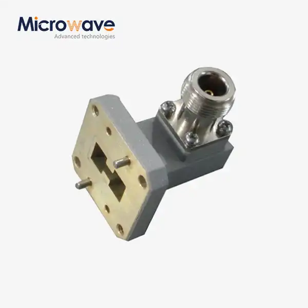 VIEW MORERight Angle Double Ridged WG To Coaxial Adapter
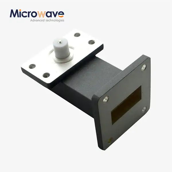 VIEW MORERight Angle Waveguide to Microstrip Adapter
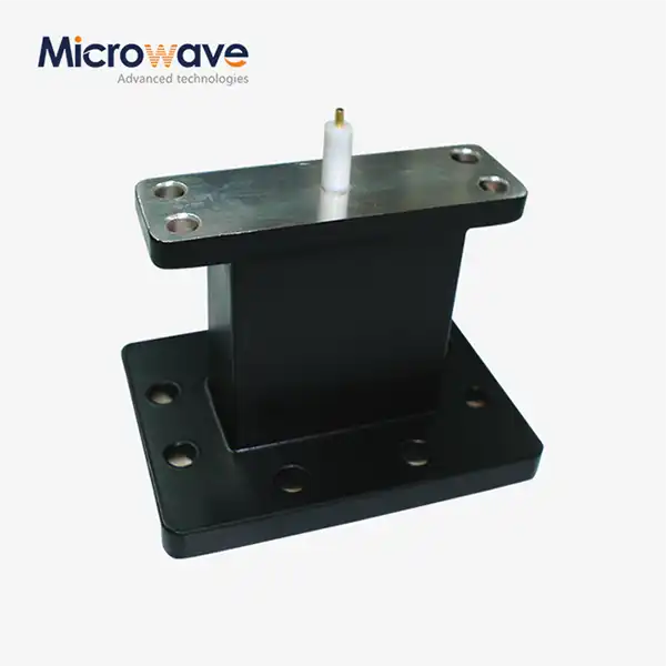 VIEW MOREEnd Launch Waveguide to Microstrip Adapter
 VIEW MORELadder Membrane Square Dual Circular Polarization Horn Antenna
