





Waveguide to Coaxial Adapter Buying Guide: Flanges, VSWR and Power
Choosing the right waveguide to coaxial adapter is one of those decisions that looks straightforward on the surface but gets complicated fast. Whether you're building a satellite ground station, integrating a radar subsystem, or running test bench evaluations, the wrong adapter choice can degrade signal quality, damage upstream components, or create integration headaches that cost far more than the part itself. This guide walks you through the specifications that matter most — flanges, VSWR, and power handling — and gives you a practical framework for making confident procurement decisions.
Understanding Waveguide to Coaxial Adapters: Basics and Operating Principles
What These Adapters Actually Do
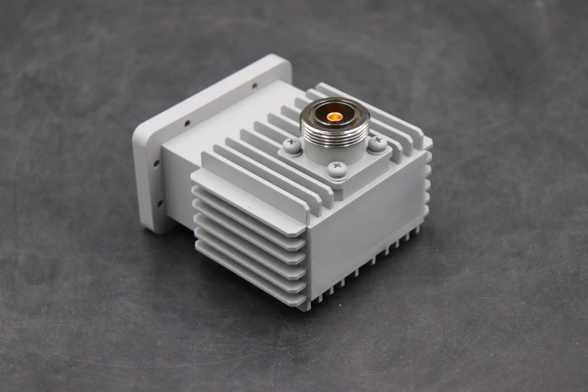
A waveguide to coaxial adapter changes radio frequency energy between two very different types of transmission lines. Signals move as a TE10 dominant mode inside a rectangular waveguide. Signals move in TEM mode along a coaxial line. The adapter connects these two modes with a probe or loop launch device that is placed to connect energy across the interface.
Impedance Matching and Signal Integrity
Matching impedance is the most difficult part of electrical work. The wave impedance of a standard rectangular waveguide changes with frequency. On the other hand, the characteristic impedance of coaxial lines like SMA or N-type connections stays at 50 ohms. The length, width, and position of the internal probe in relation to the short-circuit back wall are all set to get a low reflection coefficient across the working band.
Frequency Bands and Power Context
Adapters are made to work with certain waveguide bands. For example, the WR-90 covers the X-band (8.2–12.4 GHz), the WR-42 covers the Ka-band (18–26.5 GHz), and the WR-15 goes into the K-band millimeter wave range. VSWR and insertion loss go up a lot when you work outside the planned band. A waveguide isolator is a good partner piece for high-power transmit chains. ADM's High Power Waveguide Isolator can handle up to 1000 W of forward power with only 0.3 dB of typical insertion loss, keeping your transmitter safe from reflected energy.
Key Specifications: Flanges, VSWR, and Power Handling Explained
Flange Standards and Physical Compatibility
The connector will physically fit with your waveguide system if you choose the right flange. Most of the flanges sold in the U.S. are either UG (MIL-specification) or EIA (Electronic Industries Alliance) flanges. UG flanges, like UG-39 for WR-90, have a cover flange and a choke flange that work together to improve friction without the need for a seal. In business telecom equipment, EIA flanges are used more often. If two flanges don't match, even by a few thousandths of an inch, they create junction discontinuities that lead to return loss that can be measured.
VSWR: What the Numbers Mean in Practice
The voltage standing wave ratio (VSWR) tells you how well the waveguide to coaxial adapter sends power without reflecting it. It is thought that a VSWR of 1.0:1 is perfect. Standard passive adapters in the industry have VSWR values below 1.25:1 across the working band, and high-precision lab-grade units get even lower, to below 1.15:1. To give you an idea, a VSWR of 1.25:1 means a return loss of about 19.1 dB, which is fine for most system costs. Anything above 1.5:1 means that there is significant reflected energy that puts stress on both the source and the adapter.
Power Handling, Thermal Management, and Material Choices
The amount of power it can handle depends on the type of coaxial connector at the output, the material of the conductor, and the plating on the surface. Copper-body adapters handle higher CW power better because they conduct heat more efficiently. Aluminum-body adapters are lighter and work well with moderate power levels. At microwave frequencies, silver or gold treatment lowers the skin effect resistance. The maximum power allowed depends on the type of coaxial connection used. SMA connectors can handle about 50 W of power at lower GHz frequencies, while N-type connectors can handle a lot more power. Insertion loss also generates heat—even 0.3 dB loss at 1 kW input means that 70 W of heat needs to be dissipated.
How to Choose the Right Adapter: A Decision Support Framework
Define Your Frequency, Power, and Environment First
To begin, set three factors that will not change: the working frequency band, the highest continuous-wave power, and the environmental conditions. Temperature changes can happen from -40°C to +70°C in a military field or at high altitude. That's the temperature range that ADM's waveguide isolators are designed to handle. The adapter must keep its electrical specs over that temperature range without the flange contact becoming mechanically distorted.
Verify Flange and Connector Compatibility
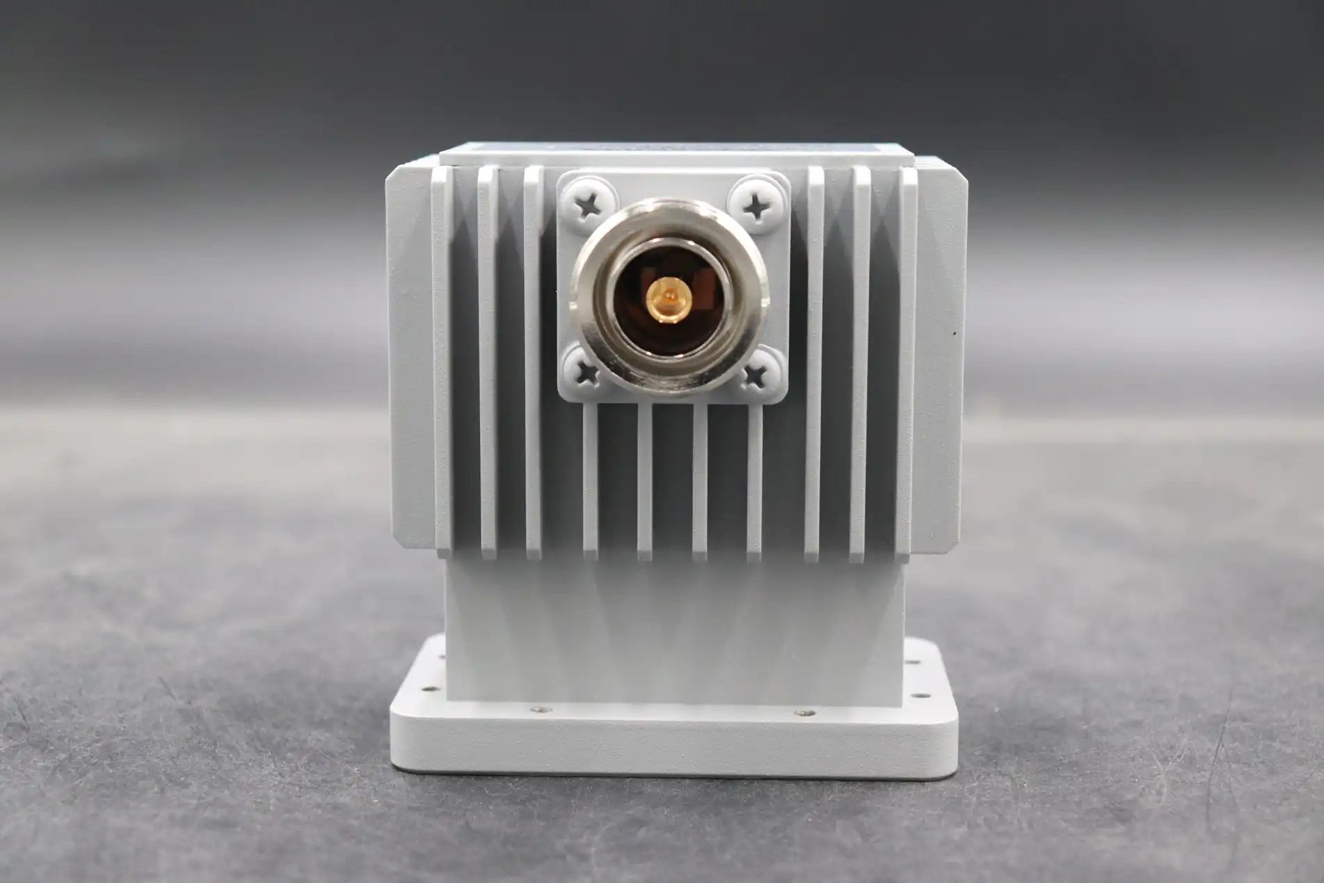
Find out what kind of flange your waveguide has before you order. Check to see if your system uses an EIA grooved flange or a UG cover/choke pair. At the coaxial port, choose the right connection type for your cable assembly based on power and frequency limits. This could be an SMA, 2.92 mm (K-connector), N-type, or TNC connector. A 2.92 mm connection raises the frequency range to 40 GHz, and N-type is better when the forward power is more than a few hundred watts.
Evaluate Supplier Reliability and Customization Capability
When buying from an OEM or a military program, a supplier's capabilities go beyond just having a list. Make sure your provider gives you full test data, such as S-parameter sweeps, and can make custom designs if normal sizes don't work for your application. ADM can customize products for OEMs in non-standard frequency bands, with different flange configurations and different materials. They can also help with prototyping and provide engineering support during the design approval process.
Popular Types and Adapter Configuration Options
Straight, E-Plane, and H-Plane Variants
The type of connector is based on how the coaxial output is physically positioned in relation to the waveguide axis. Straight adapters send the probe through the wide wall and out of the coaxial connection along the line of the waveguide. They are small and direct. In antenna feed systems, E-plane waveguide to coaxial adapters are often used to bend the coaxial port so that it is perpendicular to the waveguide's E-field plane. When the chassis geometry needs a certain routing path, H-plane adapters are used. They exit in the H-field plane.
Specialized Variants for High-Power and Test Applications
To make radar transmit chains and high-power feeding systems work best, you should use right-angle adapters with heavy-body aluminum or copper housings and air-dielectric coaxial sections. In test and measurement (T&M) settings, it is common to use precision adapters with gold-plated connectors and VSWR data sheets that have been checked separately. ADM's High Power Waveguide Isolator, which has a bandwidth of 800 MHz and a typical isolation of 20 dB, is often used with these adapters in transmit chains to soak up power that is reflected before it gets to the source.
Assessing Quality Through Documentation and Certification
A good adapter has a datasheet that shows recorded VSWR and insertion loss across the whole frequency range, not just the usual numbers at one frequency. Defense and commercial aerospace programs must start with manufacturing that is ISO 9001-certified and RoHS-compliant. All of ADM's goods are RoHS-compliant, and the company has ISO 9001:2015, ISO 14001:2015, and ISO 45001:2018 certifications. Procurement teams can attach these certifications straight to program files.
Practical Tips for Procurement: Ordering, Customization, and Bulk Purchasing
Where to Source and What to Ask
Teams in charge of buying things can get adapters from makers or from approved distributors. When you buy directly from a manufacturer like ADM, you can get engineering help, custom configurations, and discounts for buying in bulk. Ask the waveguide-to-coaxial adapter provider for measured S-parameter data, material certificates, and proof of flange standards when you are looking at them. A red flag is a chart that isn't clear and only lists "typical" temperatures at room temperature.
Before you place an order, here are the most important things you should check:
- Does the frequency range of the adapter cover the whole working band of your system?
- Is the given VSWR tested or simulated? If simulated, over what temperature range?
- What is the highest continuous-wave power rating at the highest frequency of operation?
- Can I get custom flange patterns or connector types, and how long does the lead time take?
These questions quickly weed out options that aren't good fits and give procurement managers the information they need to back up their choice of components in program paperwork.
Customization and OEM Partnership Benefits
OEM customization is the way to go when normal stock connections don't meet your electrical or mechanical needs. ADM's OEM service includes frequency-specific probe tuning, non-standard flange geometries, changed body materials, and hermetic sealing for environments with pressure or no pressure. It's easy to get a prototype quickly, and the engineering team helps with design, testing, and scaling up for production. When you buy in bulk, working directly with the maker cuts down on wait times and ensures a consistent supply chain that you can't always get through distributor channels.
Conclusion
When you choose a waveguide to coaxial adapter, you need to make sure that the flange standards, VSWR performance, power handling, and weather ratings meet the needs of your system. The choices you make about the parts have a direct effect on how reliable the system is and how much it costs to maintain over time. Because ADM has been making products for more than 20 years, has full ISO certification, and can customize products for OEMs, its product line is a reliable source for both standard and custom RF transition components for procurement engineers and system integrators.
FAQ
What VSWR value is acceptable for a waveguide to coaxial adapter?
Most system designs can handle VSWR less than 1.25:1, which is equal to a return loss of about 19 dB. VSWR below 1.15:1 is ideal for high-precision tasks like measuring antennas or making low-noise receiver chains. Always ask for measured data across the whole working band, not just a number for one frequency.
Can one adapter cover multiple waveguide bands?
Not at all. Each adapter is tuned to a certain frequency range and waveguide size. At the design frequency, the length and position of the probe are set to be a quarter of a wavelength. When you use an adapter outside of its rated band, insertion loss and VSWR go up a lot, which hurts the performance of the system.
What connector type should I choose for high-power applications?
N-type connectors are the standard for forward power above 50–100 W and can handle a lot more power than SMA connectors. Use an air-dielectric N-type interface and a copper-body adapter with enough surface area to get rid of heat for continuous-wave power that is close to 1 kW.
How do UG and EIA flanges differ?
UG flanges are made according to MIL-specs and use a cover/choke fitting pair that keeps the electrical contact good even without a seal. EIA flanges are more popular in business telecom and have touch areas that are either grooved or flat. Without an adapter plate, the two standards can't be used mechanically together.
Does ADM offer custom waveguide-to-coaxial adapters?
Yes. ADM offers full OEM customization, which includes non-standard frequency bands, changed flange patterns, material choice, and socket type. You can get help from engineers by making prototypes and increasing the size of your production. For questions about specs and wait times, email craig@admicrowave.com.
Partner with ADM for Your Next RF Component Procurement
ADM is a reliable company that makes waveguide to coaxial adapters. They have been in business for over 20 years, are ISO 9001:2015 certified, and offer a full OEM customization program. Our engineering team can make quick prototypes, provide detailed test paperwork, and offer low prices for both small and large orders. To get a price right away, email your requirements to craig@admicrowave.com.
References
1. Pozar, D. M. — Microwave Engineering, 4th Edition. Wiley, 2011.
2. IEEE Standard 1785 — IEEE Standard for Rectangular Metallic Waveguides and Their Interfaces for Frequencies of 110 GHz and Above. IEEE, 2013.
3. Collin, R. E. — Foundations for Microwave Engineering, 2nd Edition. IEEE Press / Wiley-Interscience, 2001.
4. MIL-DTL-3922 — Military Specification: Flanges, Waveguide (Choke and Cover), General Specification For. U.S. Department of Defense, 2003.
5. Montgomery, C. G., Dicke, R. H., & Purcell, E. M. — Principles of Microwave Circuits. MIT Radiation Laboratory Series, McGraw-Hill, 1948; reprinted IET, 1987.
6. Vendelin, G. D., Pavio, A. M., & Rohde, U. L. — Microwave Circuit Design Using Linear and Nonlinear Techniques, 2nd Edition. Wiley, 2005.
YOU MAY LIKE
 VIEW MORESlotted Waveguide Array Antenna
 VIEW MORECoaxial Power Detector
 VIEW MOREDouble-bend Waveguide
 VIEW MORECircular Waveguide Transition
 VIEW MORECircular Waveguide To Coaxial Adapter
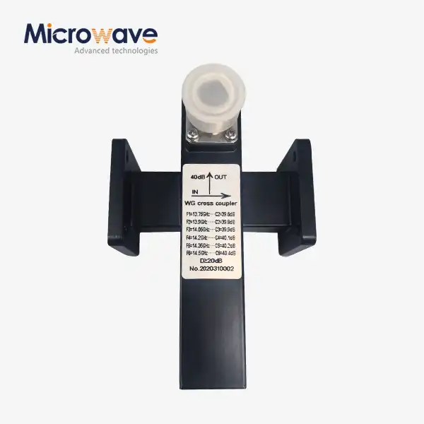 VIEW MORECrossguide Directional Coupler
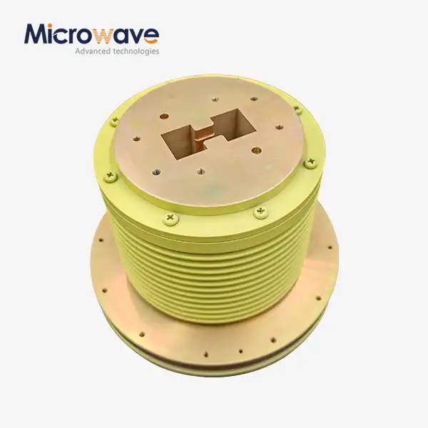 VIEW MOREDouble Ridge Waveguide Rotary Joint
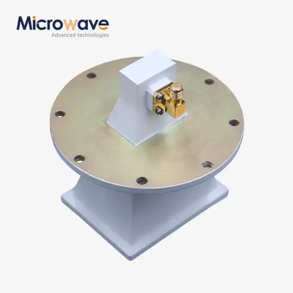 VIEW MOREPyramidal Linear Polarization Horn Antenna
