





Waveguide Section Types for Different RF Systems
When designing RF systems for satellite communication, radar, or 5G infrastructure, choosing the right waveguide configuration is crucial to performance. Waveguide sections come in multiple forms—straight, curved, flexible, and twisted—each designed to address specific transmission challenges. Among these, the straight waveguide section remains the most widely used due to its simplicity, low insertion loss, and predictable electromagnetic behavior. These rigid sections transmit microwave signals efficiently across X-band, Ku-band, and Ka-band frequencies, handling high power densities while maintaining signal integrity. Whether you're integrating waveguide assemblies into defense radar systems or satellite ground stations, understanding the structural and electrical characteristics of each waveguide type enables smarter procurement decisions and optimized system design.
Understanding Straight Waveguide Sections and Their Role in RF Systems
What Makes Straight Waveguide Sections Essential in Microwave Transmission?
A straight waveguide section is the main part of many RF designs. It guides electromagnetic waves through a thin metal tube with little loss. In contrast to coaxial lines, which use dielectric materials to split the inner and outer conductors, waveguides use their shape—usually rectangular or circular cross-sections—to contain and direct electromagnetic energy. This design gets rid of dielectric losses, which makes straight waveguide sections perfect for high-frequency uses above 1 GHz where coaxial cables have trouble keeping the signal strong.
Frequency Bands and Power Handling in Practical Applications
Straight waveguide sections are widely used in X-band (8–12 GHz) radar systems, where low loss and high power handling are essential. Defense companies depend on these parts to keep the signal quality high over long transmission lines in surveillance radars that are used in the air and on the ground. Our straight waveguide sections at Advanced Microwave Technologies Co., Ltd. can handle frequencies from 0.5 GHz to 110 GHz, which includes both old transmission bands and new millimeter-wave uses. Our ISO 9001:2015-certified manufacturing processes guarantee the accuracy of dimensions that are necessary to keep cutoff frequencies and mode purity.
Material Choices That Influence Durability and Performance
Material choice has a direct effect on how well a waveguide works when it is stressed by the surroundings. Aluminium metals are strong but light, making it good for use in aircraft. Copper and brass, on the other hand, are better at conducting electricity, making them ideal for use in laboratory-grade measurement systems. Gold or silver plating on the surface lowers ohmic losses and stops oxidation in wet marine settings. When building satellite ground stations, our buying partners often ask for tin-plated aluminum sections to be used for outdoor placements. These sections are resistant to rust and don't change temperature much from -40°C to +85°C.
Comparison of Waveguide Section Types for Different RF System Needs
Straight Versus Curved and Flexible Waveguide Configurations
Waveguide selection is based on the trade-offs between rigidity and the ability to adapt to different spaces. Because they don't bend and keep the same cross-sectional shape, straight waveguide sections have the lowest insertion loss (usually less than 0.05 dB per metre at X-band). Waveguide bends with curves, like E-plane and H-plane shapes, cause extra losses of 0.1 to 0.3 dB for every 90-degree bend, depending on the bend radius and frequency. Flexible waveguides give up some loss performance (usually 0.2 to 0.5 dB per meter) so they can be installed more easily in tight spaces or for uses that need mechanical movement, like marine antenna positioners.
Engineers carefully balance these things when they design a satellite uplink system at a telecom ground station. Straight waveguide sections are better for long transmission runs from the transmitter room to the antenna feed. On the other hand, flexible sections might be better for small changes around structural obstacles, even though they lose more signal. During the design phase, our engineering team at ADM works with system integrators to map signal paths and optimize waveguide routing. This cuts down on unnecessary losses while keeping the mechanical feasibility.
Waveguides Versus Coaxial Cables and Microstrip Lines
When you compare transmission media, you can see why waveguides are the best choice for high-power, high-frequency tasks. Because of dielectric absorption and skin effect losses, coaxial lines lose signal strength above 18 GHz. This means they can't be used for Ka-band satellite connections. Even though microstrip lines are small and easy to add to PCBs, they lose power through radiation and can only handle a few watts at most. Straight waveguide sections can handle kilowatts of continuous power without breaking down due to heat, which is why they are essential in high-power radar emitters and satellite Earth station HPAs.
Waveguides' ability to work in a wide range of environments gives another level to this comparison. When connectors rust or dielectrics absorb water, coaxial cables lose their performance. But waveguide flanges that are properly sealed will keep working even after decades of being outside. Defence procurement teams choose pressurised waveguide systems for important radar installations. These systems keep the insides dry with nitrogen or air, which stops condensation that could mess up signal transmission when temperatures change.
Rectangular Versus Circular Cross-Section Waveguides
Cross-sectional shape affects how waves propagate and the limits of mechanical integration. Rectangular waveguides, which are standardised under names like WR-90 (X-band) and WR-62 (Ku-band), allow for dominating TE₁₀ mode transmission with well-known electrical parameters. Their flat fixing surfaces make it easier to connect flanges and place racks in equipment cases. While circular waveguides can handle rotating polarization in satellite communication feeds and help certain modes travel with less loss, their radial symmetry makes it harder to set up small systems.
When building phased array radars, business-to-business customers usually choose rectangular parts. This is because they allow for stacking or arranging multiple waveguides with little empty room. In places where mechanical spinning is needed but signal transmission must not be interrupted, circular parts are used in rotary joints and polarization-agile antenna feeds. At ADM, we can make unique parts with any shape, and our precise CNC machining makes sure that important internal measurements are within ±0.025 mm of tolerance.
How to Select the Best Waveguide Section for Your RF System: A Decision-Making Framework?
Evaluating Frequency Compatibility and Bandwidth Requirements
The first thing you need to do when choosing a waveguide is to make sure that the section's cutoff frequency is in line with your working band. Each waveguide standard has a cutoff frequency below which propagation stops. Working too close to the cutoff frequency causes more losses, and working too far above the cutoff frequency can cause higher-order modes to excite. With a cutoff frequency of 6.56 GHz, a WR-90 straight waveguide section works best in the 8.2–12.4 GHz (X-band), giving you enough room for both cutoff and multimode operation.
Modern 5G millimeter-wave systems that work at 28 GHz or 39 GHz need waveguides with smaller openings, such as WR-28 or WR-22. To make sure that signal reflections stay below acceptable levels, procurement teams must check that the specifications provided by suppliers include single-mode bandwidth guarantees and VSWR (voltage standing wave ratio) data. At ADM, our test facilities use vector network analyzers that are set to 110 GHz. These analyzers measure S-parameters (S₁₁, S₂₁) to check insertion loss and return loss across the full stated frequency before the goods are shipped.
Power Handling and Thermal Management Considerations
How much power a waveguide can handle at its peak and on average depends on its aperture, wall thickness, and surface finish. At X-band, a WR-90 straight waveguide section with a normal wall thickness can handle about 1 MW of peak power and 50 kW of average power before the voltage breaks down or the heat changes. For high-duty-cycle radar or continuous-wave satellite uplinks, thermal analysis is needed to keep hotspots from forming at flange joints or along parts that don't have good thermal contact with heat sinks.
Defence contractors who put waveguides into radar pods that fly in the air must also think about how to handle power. Our aluminum alloy parts have a good strength-to-weight ratio and can still hold enough power for pulse-compressed radar patterns. During OEM collaboration, custom thermal coatings and forced-air cooling interfaces can be added to make sure thermal stability without affecting electromagnetic performance.
Custom OEM Solutions for Specialized Industrial Requirements
Straight waveguide sections that are already made can meet a lot of needs, but mission-critical systems often need custom solutions. When research institutions build experimental antenna arrays, they need waveguides with non-standard lengths, fixing holes, or filter structures built right in. Through OEM partnerships, it is possible to work together on designing waveguide assemblies that fit directly into larger subsystems. These assemblies come with mounting brackets, environmental sealing, and certain types of flanges (UG, CPR, or custom).
We at Advanced Microwave Technologies Co., Ltd. have been making custom waveguides for aircraft and defense companies for 20 years. Our prototyping services give the first models within two to three weeks, so you can make sure the idea works before committing to making a lot of them. Technical support doesn't end with delivery; our engineers help with installation, troubleshoot insertion loss, and make changes in the field when system requirements change during deployment.
Ensuring Quality Through Certified, Reputable Manufacturers
Getting qualified suppliers is the first step in lowering procurement risk. ISO 9001:2015 and RoHS compliance are signs of advanced quality management systems and environmental responsibility. However, more in-depth research looks at how well the product can be manufactured and how measurements can be tracked. Suppliers should give test reports that can be linked to national metrology institutes like NIST in the US. These reports should show any errors in the dimensions, the roughness of the surface, and how well the electrical system works.
At ADM, our 24-meter Microwave Darkroom is an example of the kind of infrastructure that serious waveguide manufacturers keep up. Far-field antenna tests and waveguide characterisation can be done at this site, which is far enough away to prove performance in real-world propagation circumstances. Procurement managers should ask waveguide providers about their measurement tools, how often they need to be calibrated, and if they have access to technical experts who can help with connection issues at any point in the product's lifecycle.
Procurement Guide: Ordering and Managing Straight Waveguide Sections for Industrial Use
Balancing Cost, Lead Times, and Order Volume
Getting straight waveguide sections means figuring out how to deal with cost models that change based on the number of orders and the level of customization. Standard catalogue sections with common lengths and flanges have the shortest lead times (often two to four weeks) and the best prices because of economies of scale. Lead times can be up to six to ten weeks longer if you need custom lengths, exotic materials, or integrated components. However, these assemblies are better for certain system architectures.
OEMs that are making a lot of radar or communication systems will notice the effect of volume pricing. Blanket purchase orders with planned releases help keep inventory costs under control and make sure that prices will stay the same during contract times. When you work with suppliers, be clear about your yearly number forecasts and any changes that might happen. This will help the suppliers use their production capacity and raw materials more efficiently, which can often lead to better pricing.
Leveraging Customization Through OEM Partnerships
When OEMs work together, waveguide procurement goes from being a one-time deal to a strategic relationship. Co-developing feed networks that combine straight waveguide sections, filters, and power dividers into single assemblies gives system integrators building satellite ground stations a competitive edge. By cutting down on the number of possible failure points, this integration cuts down on the work that needs to be done in the field to put the parts together. It also minimizes the loss of power during connections.
During the customization process, it's important to have thorough specs on things like electrical performance, mechanical interfaces, and environmental qualification. Misunderstandings can cause shipping delays or goods that don't meet standards if there isn't clear documentation. The engineering team at ADM carefully looks over customer requirements and gives design-for-manufacturability comments that strike a balance between performance goals, the ability to make the product, and cost goals. This consultative strategy has helped projects like UAV communication lines and maritime navigation radar systems succeed.
Requesting Samples and Utilizing Technical Support
Requesting samples for functional testing and integration validation lowers risk before committing to large amounts of production. Bench measures of insertion loss and VSWR, dimensional inspection of flange surfaces, and mechanical fit-checking within the target system should all be part of the sample evaluation process. Finding problems with measurements or performance during the sample phase saves a lot of money on redesigns or retrofits that have to be done after full-scale production starts.
The technical help doesn't end with the sale. When there are problems during installation, like flange alignment issues or torque requirements for flange bolts, the supplier can help. Our ADM support team gives clear instructions on how to install things, how much torque to use to keep the flange from warping, and how to fix problems at the system level. Having access to applications engineers who know both waveguide theory and straight waveguide section integration and how to integrate systems in real life speeds up the process of solving problems and boosts trust in the supply relationship.
Conclusion
When choosing the right waveguide section types, you need to pay close attention to the frequency characteristics, the power handling, the mechanical limitations, and the supplier's capabilities. Straight waveguide sections are still important parts of high-performance RF systems because they offer the best loss performance and power capacity when they are properly specified and sourced. Procurement pros get parts that make systems more reliable and effective by comparing different waveguide designs, checking out materials and cross-sectional geometries, and working with approved makers. The frameworks shown here give B2B clients useful tools for making smart choices, lowering the risk of procurement, and building supply relationships that will help their operations succeed in the long term.
FAQ
1. What frequency ranges do standard straight waveguide sections support?
Standard straight waveguide sections are identified by alphanumeric codes that match certain frequency bands. In the X-band, WR-90 parts work between 8.2 and 12.4 GHz; in the Ku-band, they work between 12.4 and 18 GHz; and in the Ka-band, they work between 26.5 and 40 GHz. Each name gives information about the inside measurements that establish the cutoff frequency and single-mode working range. This makes sure that electromagnetic waves can travel properly without any higher-order mode disturbance.
2. How do I figure out which waveguide pieces or coaxial lines will work best for my project?
Straight waveguide sections work really well in high-power (above 18 GHz) and high-frequency (below 18 GHz) situations where low loss and stable temperature are important. For low frequencies and middling power levels, coaxial cables are flexible and easy to place. When signal integrity over long distances or high power densities are important, like in satellite uplinks or radar transmitters, waveguides work better even though they are harder to set up.
3. What material selections maximize waveguide performance in harsh environments?
Aluminum metals that have been protected by anodizing or chromate conversion are resistant to rust and can be used outside. In precision measurement systems, insertion loss is kept to a minimum by plating copper or brass with silver or gold. Using gaskets or O-rings to seal the environment stops moisture from getting in, and pressurising with dry gas gets rid of condensation inside. When choosing a material, you should think about the working temperature range, the amount of humidity, and any vibration or shock needs that are unique to your deployment area.
Partner With ADM for Precision-Engineered Straight Waveguide Section Solutions
Advanced Microwave Technologies Co., Ltd. has been making high-precision waveguide assemblies for difficult RF uses for more than 20 years. Our designs for straight waveguide sections can handle frequencies from 0.5 GHz to 110 GHz. They are backed by ISO 9001:2015 quality certification and strict testing in our ultra-modern 24-meter microwave darkroom. Our engineering team works closely with your technical staff to provide solutions that improve performance and dependability, whether you need standard catalogue parts or custom OEM kits for defence radar, satellite communication, or aerospace navigation systems. Contact craig@admicrowave.com right away to talk about your waveguide purchasing needs, get technical specs, or set up a trial sample. Our dedication to quality production and quick support will help your RF system reach its full potential.
References
1. Pozar, David M. Microwave Engineering, 4th Edition. Hoboken: John Wiley & Sons, 2011.
2. Balanis, Constantine A. Advanced Engineering Electromagnetics, 2nd Edition. Hoboken: John Wiley & Sons, 2012.
3. Collin, Robert E. Foundations for Microwave Engineering, 2nd Edition. Hoboken: Wiley-IEEE Press, 2001.
4. Marcuvitz, Nathan. Waveguide Handbook. London: Peter Peregrinus Ltd., IEE Electromagnetic Waves Series, 1986.
5. Saad, Theodore S. Microwave Engineers' Handbook, Volume 1. Dedham: Artech House, 1971.
6. Harvey, A.F. Microwave Engineering. London: Academic Press, 1963.
YOU MAY LIKE
 VIEW MOREWaveguide Adapter
 VIEW MORECustom WG to Coaxial Adapter
 VIEW MOREWG Twist
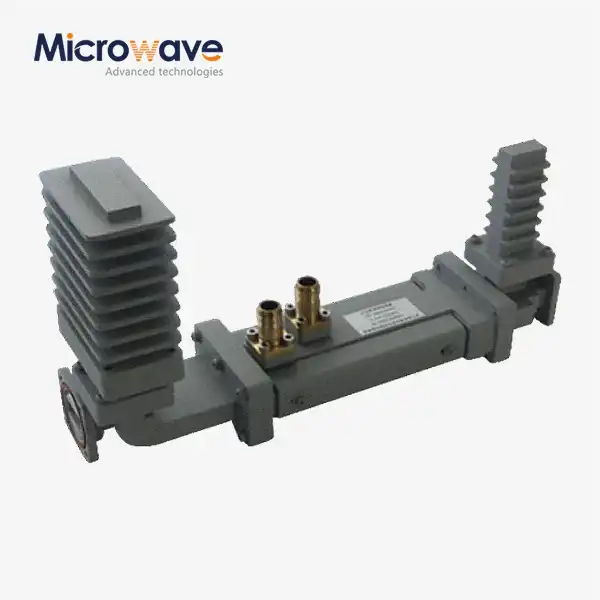 VIEW MOREHigh Power Waveguide Differential Phase Shift Isolator
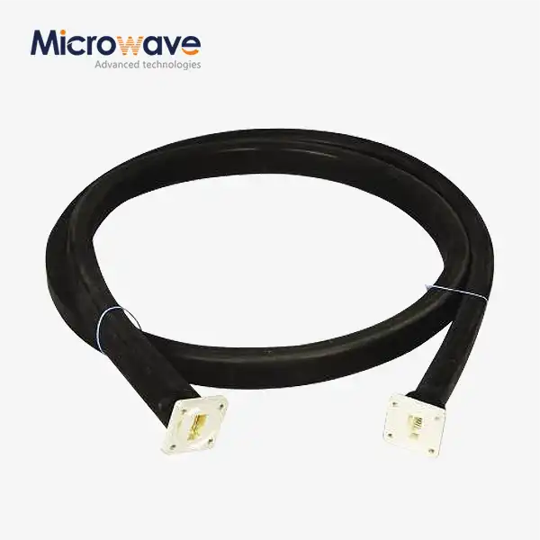 VIEW MOREWaveguide Cable Assembly
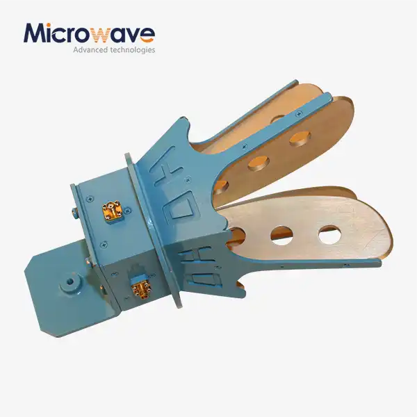 VIEW MOREOpen Boundary Dual Linear Polarization Four Ridged Horn Antenna
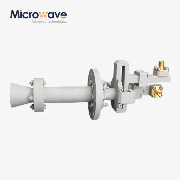 VIEW MOREConical Dual circular Polarization Horn Antenna
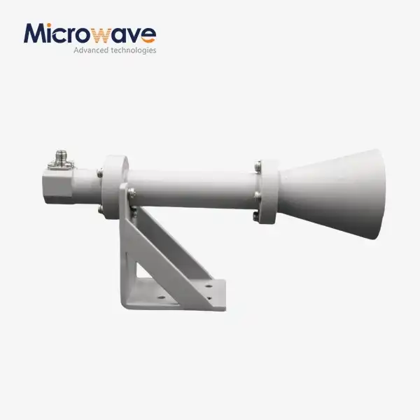 VIEW MOREDual Linear Broadband Circular Polarization Horn Antenna
