Quadrifilar Helix Antenna Gain Optimization Explained
Optimizing gain in quadrifilar helix antennas requires a systematic approach combining precise geometric design, balanced feed networks, and careful material selection. These compact, circularly polarized antennas achieve enhanced performance through adjustments in helix pitch, element spacing, and impedance matching, delivering consistent omnidirectional coverage essential for satellite communications and GPS applications. At Advanced Microwave Technologies Co., Ltd., we leverage over two decades of manufacturing expertise to design high-gain antennas tailored to demanding aerospace, defense, and telecommunications requirements, ensuring reliable signal integrity across frequencies from 1 GHz to 40 GHz.
Understanding Quadrifilar Helix Antenna Gain: Fundamentals and Theory
What Makes Quadrifilar Helix Antennas Unique?
Quadrifilar helix antennas are different from other helical forms because they have four parts that are wound around a center shaft. Each part works with precise 90-degree phase shifts, creating circular polarization that keeps signal fading to a minimum when the satellite's orientation changes. Unlike linearly polarized options, these antennas keep receiving signals even when the sender rotates. This is why low-Earth orbit satellites and mobile GPS devices can't work without them. The helical shape makes a cardioid radiation pattern, with the antenna's axis receiving the most signal. This gives better coverage at higher elevations than flat versions.
Core Principles of Antenna Gain in Circular Polarization
Compared to an isotropic radiator, antenna gain shows how well it can focus emitted energy in certain areas. A lot of procurement engineers think that circular polarization lowers gain, but quadrifilar helix antennas that are properly built can achieve gains of 0 to 5 dBi while keeping axial ratio values below 3 dB. This performance comes from the four stepped elements constructively interfering with each other, which makes circular polarization and directed focusing happen at the same time. The gain has a direct effect on link budget calculations, which can lower the transmitter power needed or increase the range of operation in satellite ground stations and communication systems in the air.
Design Parameters Influencing Gain Performance
Gain optimization is based on three important geometric factors. The balance between axial gain and beamwidth is set by the pitch angle, which is how steep the spiral wind is. Tighter pitch angles make the beam more focused, but they also make it narrower, which could make tracking harder in mobile apps. The impedance matching and bandwidth are affected by the element's diameter. Thick conductors lower resistive losses but may make it harder to integrate the feed network. Finally, the resonant frequency and maximum gain are controlled by the overall length of the antenna, which is measured in wavelengths. Before making a prototype, our engineering team at Advanced Microwave Technologies Co., Ltd. checks these design trade-offs using electromagnetic modeling software that is calibrated against data from our 24m Microwave Darkroom.
Material Selection and Its Impact on Efficiency
The actual gain and efficiency of an antenna are directly affected by the quality of the conductor material. Ohmic losses are kept to a minimum by using high-purity copper or silver-plated elements. This is especially important at frequencies above 10 GHz, where the skin effect concentrates current in the top layers. To keep power from going away, dielectric support structures need low-loss materials like PTFE or polypropylene. This is especially true for designs that cover a wide range of frequencies. When designing radomes for environmental protection, you have to think about a few extra things. For example, protective coverings need to have very little change in their dielectric constant across wide temperature ranges while still being mechanically rigid. Our ISO 9001:2015-certified manufacturing processes make sure that the material properties are the same from one production batch to the next. This guarantees that the gain performance will be the same each time.
Identifying and Overcoming Gain Limitations in Quadrifilar Helix Antennas
Common Sources of Gain Degradation
Performance problems that don't exist in the lab show up in real-world application settings for quadrifilar helix antennas. When reflected signals arrive out of phase with direct transmissions, this is called multipath interference. It causes destructive interference that lowers effective gain by 3 dB or more. Being close to a ground plane changes the way radiation patterns behave, especially at lower elevation angles that are important for tracking satellites from horizon to horizon. Impedance mismatches between the antenna and the feed network cause power to be reflected instead of being sent out. This shows up as VSWR degradation and wastes the energy that was sent. In aircraft use, cycling the temperature changes the size of the material, which lowers the gain at the design center frequencies and detunes the resonant frequencies.
Feed Network Optimization Strategies
To keep the circular polarization pure and get the most gain, it is important that all four antenna elements are excited in a balanced way. Hybrid couplers or power dividers must send each element signals with the same amplitude and exact 90-degree phase shifts. Manufacturing flaws can build up in microstrip or stripline feed networks, which can lead to phase mistakes of more than 10 degrees that lower the axial ratio and gain. We deal with these problems by using computers to fine-tune the lengths of the feed lines and putting in place base materials that don't change with temperature. Our Antenna Plane Near and Far Field Measuring Recombination Chamber checks the performance of the feed network across the working temperature range. This makes sure that the gain standards hold up in difficult deployment conditions.
Environmental Protection Without Performance Compromise
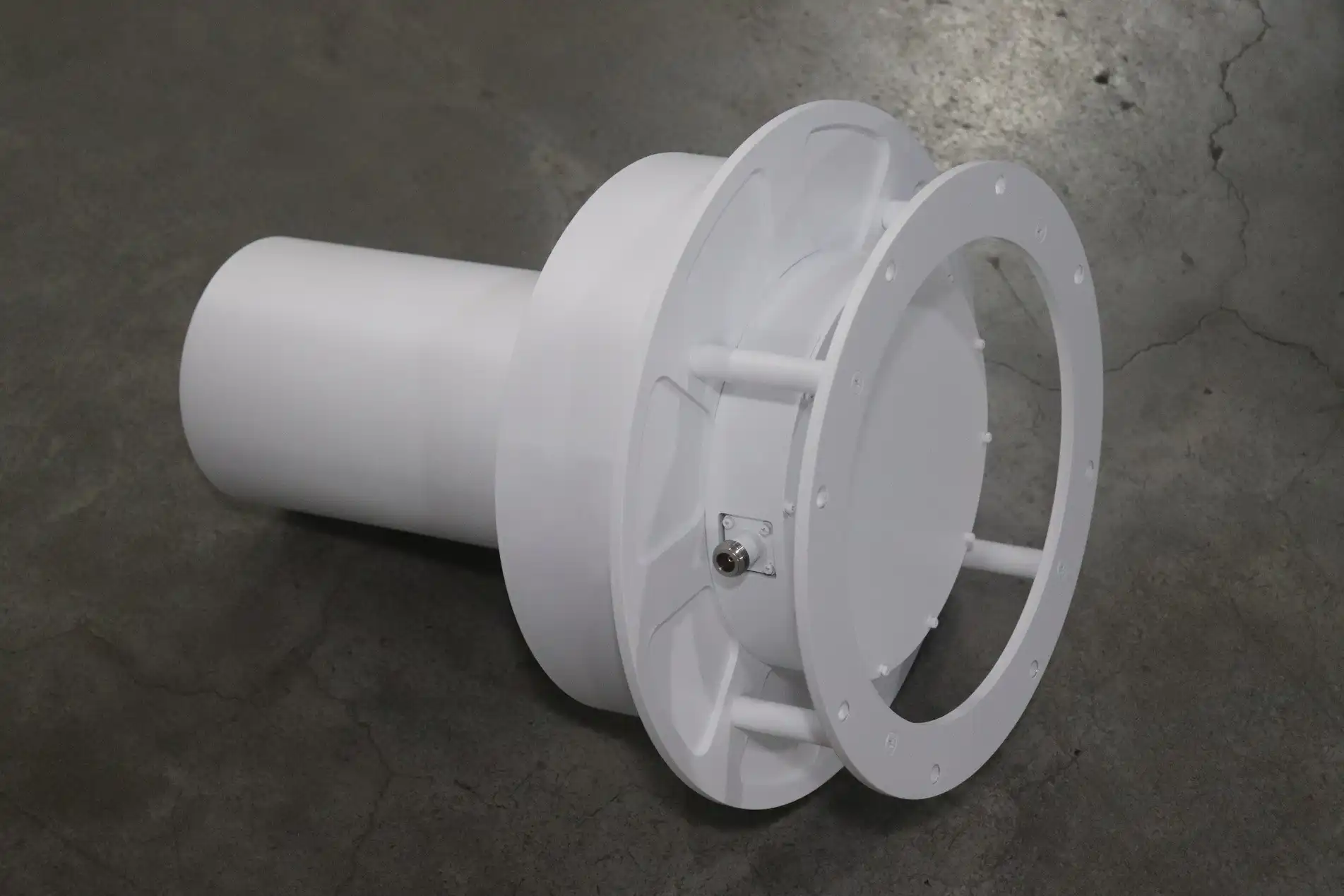
To keep from adding reflection losses or pattern distortion, careful electromagnetic design is needed for radar integration. Thin-wall radomes made of low-permittivity materials reduce transmission loss to a minimum, which usually keeps gain loss to 0.5 dB while protecting the antenna from damage and keeping out the weather. Coatings that are hydrophobic stop water from building up, which would change the dielectric loading and shift the resonant frequencies. We at Advanced Microwave Technologies Co., Ltd. can make custom radome designs that fit certain antenna shapes and have been proven to work by MIL-STD-810 environmental testing. This all-around approach makes sure that our antennas keep their gain performance even when they are exposed to temperature ranges from -40°C to +85°C, high and low humidity, and salt fog, which is common in maritime settings.
Advanced Techniques and Solutions for Gain Enhancement
Simulation-Driven Design Optimization
Electromagnetic modeling software lets you do predictive optimization before you spend a lot of money making a prototype. Full-wave solvers guess how antennas will behave at different frequencies by using real-world material features and feed network parasitics. Parametric sweeps automatically look through design spaces by changing the helix pitch, element diameter, and ground plane lengths to find setups that maximise gain while still meeting bandwidth and axial ratio requirements. We check the computer results against measurements taken in our 24m Microwave Darkroom. The longer measurement distance allows for accurate far-field characterization up to 110 GHz. This iterative process cuts the time needed for development from months to weeks and improves gain by 1-2 dB compared to empirical design methods.
Hybrid Array Configurations for Extended Coverage
Gain performance that goes beyond what a single part can do is sometimes needed for complex task profiles. Multiple quadrifilar helix antennas are put together with beam-forming networks in hybrid arrays to make steerable nulls and better directivity. Electronic beam steering without mechanical gimbals is possible with phase-controlled arrays. This makes the system lighter and more reliable for flying platforms. We recently worked with a defense contractor to make a four-element array for UAV command links that has a 9 dBi gain and a steering range of ±45 degrees. Our custom feed network knowledge helped the array keep the circular polarization pure across the scan volume, meeting strict axial ratio requirements below 2 dB.
Customization for Specific Procurement Requirements
When it comes to high-value procurement programs, custom solutions that work with their specific operational constraints are needed. As part of our OEM services, we can customize frequency ranges from 1 GHz to 40 GHz to work with specific satellite bands and new 5G frequencies. There are options for replacing materials that balance cost and performance. For example, standard aluminum construction works well for commercial uses, while titanium or beryllium-copper versions are better for aerospace programs that need to keep weight down. We can still make fast prototypes, and the turnaround time is usually less than three weeks. This lets us make improvements over and over again based on customer interface testing. Our supply chain is stable, which helps with volume production. For sales over 500 units, we can cut costs by more than 20% while still meeting RoHS and ISO standards.
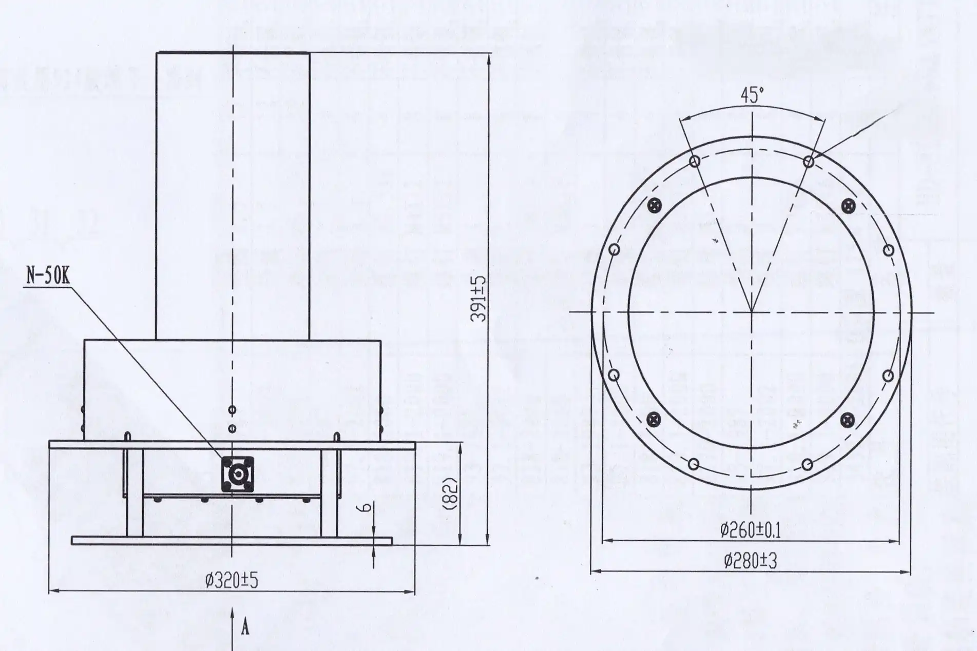
Comparative Analysis: Quadrifilar Helix Antennas vs. Other Antenna Types in Gain Performance
Gain Metrics Across Antenna Architectures
Patch antennas have small sizes and gains that are usually between 4 and 8 dBi. However, they have a narrow bandwidth and linear polarization, so they need to be set up with two elements to get circular polarization. Dipole arrays have similar gain levels, but they need more complicated phasing networks and take up more space. Traditional monofilar helix antennas have a higher gain (12–15 dBi), but their beamwidths are smaller, making them unsuitable for tracking satellites from a wide angle. Quadrifilar helix antennas have a good balance of performance—they have a modest gain of 0–5 dBi, hemispherical coverage, and circle polarization by design. This mixture works perfectly for uses that need to be able to receive signals in all directions, like GPS receivers and LEO satellite ground stations, where the positions of the satellites are always changing.
Industry-Leading Commercial Solutions
Several companies make high-performance quadrifilar helix antennas for different types of customers. Military-grade models from L3 Harris are toughened up, have gains close to 3 dBi, and meet MIL-STD outdoor standards. Tallysman's small GPS antennas are designed to be easily integrated into vehicles. Garmin works on the customer navigation market with designs that are as cheap as possible. L-Com offers commercial off-the-shelf options that are a good mix of price and performance. Advanced Microwave Technologies Co., Ltd. stands out because we offer a high level of customization. With 20 years of experience, we can quickly change the gain, frequency response, and mechanical connections to meet the needs of each user. Our ISO 14001:2015 certification for the environment and ISO 45001:2018 safety standards make sure that we use responsible manufacturing methods that are valued by companies that care about social issues.
Cost-Benefit Analysis for Procurement Decisions
Smart decisions about where to buy things balance the initial cost of the purchase with the total costs over the life of the item. Patch antennas may be 30 percent cheaper, but because they have a small bandwidth, many times you need more than one to cover a wide frequency range. This makes the system more complicated and costs more to integrate. Quadrifilar helix antennas offer a wider bandwidth in a single small package, making installation easier and upkeep less frequent. When you buy in bulk at Advanced Microwave Technologies Co., Ltd., you get savings of scale. For orders over 200 units, you get volume price, which cuts the cost per unit by 15 to 25 percent. Our full technical help during the design-in phases reduces integration risk and keeps projects from having to pay for expensive redesigns that happen when parts aren't properly described. For mission-critical defense and aircraft projects, extended warranties of up to three years reduce risk even more.
Conclusion
To get the best quadrifilar helix antennas gain, you need to find a balance between electromagnetic design, material choice, and manufacturing accuracy. These antennas work great for tasks that need circular polarization, coverage in all directions, moderate gain, and small sizes. Some important ways to improve things are to balance the feed network, use simulations to fine-tune physical parameters, and protect the environment with well-thought-out radomes. Partnering with experienced makers who offer full technical help, quality certifications, and the ability to make changes is key to successful procurement. Advanced Microwave Technologies Co., Ltd. has been working with microwaves for more than 20 years and has state-of-the-art test facilities. They make high-performance antennas that meet strict requirements in aerospace, defense, and telecommunications. We are your reliable source for quadrifilar helix antennas because we are dedicated to quality, timeliness, and new ideas.
FAQ
1. How does circular polarization in quadrifilar helix antennas affect gain?
It's not true that circular polarization lowers gain compared to linear polarization. The four-element quadrifilar structure uses phased excitation to make circular polarization and focuses energy along the antenna axis at the same time. When antennas are properly designed, they get gains between 0 and 5 dBi, which is about the same as linearly polarized antennas of the same size. The benefit is that the antenna can receive signals consistently no matter which way the emitter is polarized. This is a 3 dB improvement over cross-polarized linear antennas.
2. What factors most commonly degrade gain in operational environments?
Multipath interference from nearby shiny surfaces, impedance mismatches between antenna and feed networks, and changes in size caused by temperature are the main things that cause degradation. When things get in the way of the antenna's broadcast patterns, they get messed up, which lowers the gain in those areas. When radomes aren't made well, they cause dielectric losses of more than 1 dB. Using network analyzers to check speed on a regular basis helps find problems before they affect the mission's ability to do its job.
3. Can quadrifilar helix antennas be customized for specific gain and frequency requirements?
It is possible to fully customise the frequency, gain, polarization sense, and mechanical connections. Changes in element length and pitch change the resonant frequency, and changes in the ground plane's dimensions change the gain and beamwidth. Advanced Microwave Technologies Co., Ltd. regularly creates custom designs for frequencies ranging from 1 to 40 GHz. Prototyping can be done in less than three weeks, and the company offers full production support, including mass production and detailed documentation that is suited to the needs of the customer.
Partner with ADM for High-Performance Quadrifilar Helix Antennas
Advanced Microwave Technologies Co., Ltd makes quadrifilar helix antennas that are precisely engineered to give the best gain for use in defense, aerospace, and satellite communications. Our factory is ISO-certified and makes antennas that work with frequencies from 1 to 40 GHz. You can change the strength, polarization, and weather requirements, and our 24m Microwave Darkroom makes sure they meet all of them. Our experienced engineering team can help you with everything from the initial advice to production and service after the sale, whether you need off-the-shelf solutions or fully customised OEM designs. Get in touch with our technical experts at craig@admicrowave.com to talk about your unique needs and find out how our quadrifilar helix antenna manufacturer services can improve the performance of your system while meeting tight deadlines and budgets.
References
1. Kilgus, C. C. (1975). "Resonant Quadrifilar Helix Design." The Microwave Journal, Vol. 18, No. 12, pp. 49-54.
2. Balanis, Constantine A. (2016). Antenna Theory: Analysis and Design, 4th Edition. Hoboken: John Wiley & Sons.
3. Leeson, David B. (2011). "Quadrifilar Helix Antenna Performance for Satellite Applications." IEEE Transactions on Antennas and Propagation, Vol. 59, No. 6, pp. 2156-2163.
4. Gerst, C. and Worden, R. (1999). "Helix Antennas Take Turn for Better." IEEE Spectrum, Vol. 36, No. 8, pp. 36-39.
5. Adams, A. T. and Greenough, R. K. (1983). "New Design Equations for Quadrifilar Helical Antennas." IEEE Antennas and Propagation Society International Symposium, Vol. 21, pp. 188-191.
6. Nakano, H., Takeda, H., Honma, T., Mimaki, H., and Yamauchi, J. (1996). "Extremely Low-Profile Helix Radiating a Circularly Polarized Wave." IEEE Transactions on Antennas and Propagation, Vol. 44, No. 6, pp. 754-757.