Waveguide Bandpass Filter Design for High Frequency Applications
High-frequency systems operating above 10 GHz demand signal selectivity that conventional filter technologies struggle to deliver. Waveguide bandpass filters, or WG bandpass filter designs, address this challenge by leveraging hollow metallic structures to propagate electromagnetic waves with minimal loss. These filters excel in applications ranging from satellite ground stations to military radar systems, where precision signal control directly impacts mission success. Their robust construction and superior power handling make them indispensable in aerospace communications, 5G infrastructure, and research instrumentation requiring reliable frequency discrimination across X-band, Ku-band, and Ka-band spectrums.
Understanding Waveguide Bandpass Filters: Principles and Design Essentials
Electromagnetic Wave Propagation in Waveguide Structures
One of the best things about WG bandpass filters is that they can send electromagnetic energy through hollow tubes that are conductive. Waveguides can support both transverse electric (TE) and transverse magnetic (TM) modes, which makes it possible for very low insertion loss at millimeter-wave frequencies. This is different from coaxial systems, which use insulating materials. The lower operational limit is set by the cutoff frequency; signals above this threshold can travel efficiently. Because they are easier to use, rectangular waveguides are most common in commercial designs. On the other hand, circular waveguides are used for specific tasks that need to be able to change the polarisation.
Critical Performance Parameters Driving Filter Selection
In procurement specifications, the effectiveness of a filter is defined by three factors. Frequency response tells us the passband width, which is the range of frequencies where signals can travel without being weakened. This is usually measured with network analyzers between 0.5 and 110 GHz. Bandwidth affects selection; narrow designs ignore neighbouring channels when the spectrum is busy, while wideband designs can handle modulated messages. Temperature stability deals with the effects of thermal expansion that change the center frequencies of defence systems that are subject to temperatures ranging from -40°C to +85°C. Contractors in the aerospace industry look for screens with drift values that are less than 0.001% per degree Celsius.
Materials Science: Balancing Conductivity and Durability
Aluminum alloys are the most common choice for cost-sensitive uses because they are easy to shape and conduct electricity well. Copper or silver-plated brass is used in high-reliability systems to keep resistive losses to a minimum. This is especially important in high-power radar transmitters that are more than 1 kW. Electroplated coats bring down the hardness of the surface to sub-micron levels, which has a direct effect on insertion loss. The newest designs use composite materials to make airborne platforms lighter. This saves 30% of the mass without affecting the electromagnetic performance. Environmental sealing makes things less likely to rust when they are used at sea.
Design Validation Through Simulation Before Fabrication
These days, electromagnetic simulation tools like HFSS and CST Microwave Studio are used in the creation process to guess how filters will behave before the metal is cut. With an accuracy of less than 0.1 dB, these tools can model cavity resonances, coupling iris dimensions, and impedance matching networks. Parametric sweeps find the best designs across all frequency bands, and thermal-electromagnetic co-simulation checks how well they work when they are under a lot of stress. This upfront engineering cuts prototype iterations by 60%, which speeds up the time it takes for OEM integrators to get their products on the market. Along with our 24m Microwave Darkroom, Advanced Microwave Technologies Co., Ltd uses these methods for full far-field verification.
Comparative Analysis: WG Bandpass Filters vs Other Filter Types
Insertion Loss: Where Waveguides Dominate
WG Bandpass Filters have insertion losses that are less than 0.5 dB across all passbands, which is a thousand times better than microstrip designs. Cavity filters have about the same level of performance, but they take up more space. Dielectric resonator filters fill in the blanks in small devices, but they can only handle a certain amount of power. At 18 GHz, a standard WG bandpass filter keeps a loss of -0.3 dB, while ceramic types with the same function lose -2.1 dB. This efficiency means that satellite uplinks can send signals over longer distances and radar front-ends can receive signals more clearly.
Power Handling Capacity Across Technologies
High-power radar systems need filters that can handle peak pulse and continuous wave powers of kilowatts or more. Waveguide filters, including WG Bandpass Filter solutions, work really well in this case because their large internal cavities effectively dissipate heat, and they can handle 5 kW of power on average in X-band applications. Microstrip filters usually stop working above 100W because the dielectric breaks down. Ceramic filters are in the middle, handling around 500W, but they need to be actively cooled. When defense companies buy parts for airborne early warning systems, they ask for different types of waveguide filters to make sure the signals stay strong during long operations.
Electromagnetic Compatibility and Shielding Effectiveness
Enclosed metal structures naturally protect against EMC, stopping unwanted emissions and outside interference. This benefit is also found in cavity filters, but microstrip versions need extra shielding casings that add to the cost. A study that compared waveguide filters to unshielded planar alternatives in 5G base station deployments found that they cut down on interference from adjacent channels by 15 dB. This shielding is very important in dense antenna arrays where crosstalk hurts the performance of multiple channels. Manufacturers that follow ISO 9001:2015, such as ADM, make sure that EMC performance is good by testing it thoroughly in a room.
Procurement Insights: How to Source and Purchase WG Bandpass Filters?
Decoding Technical Specifications on Price Lists
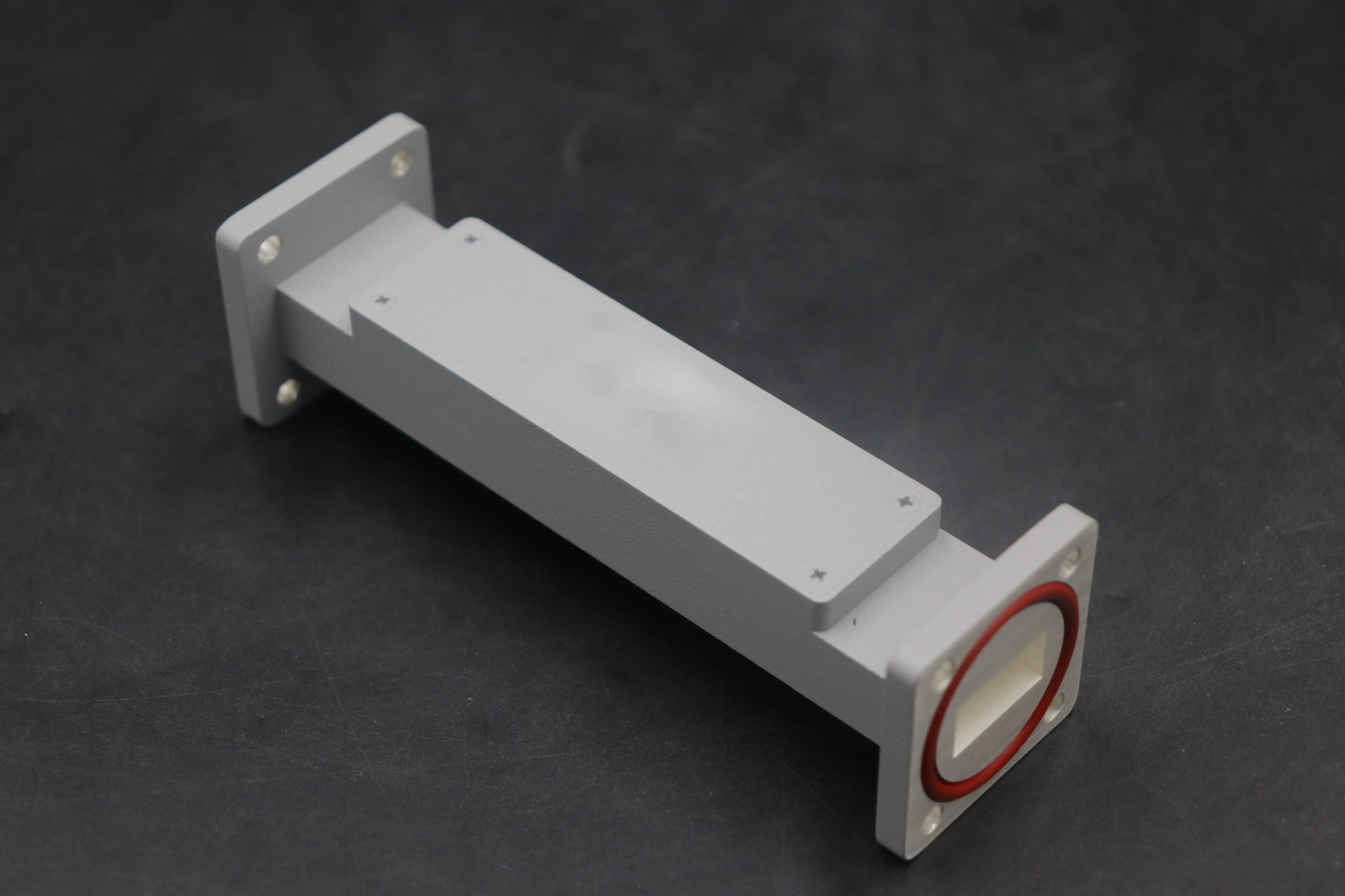
When buying something, procurement teams come across specs that show center frequency, partial bandwidth, and return loss. The passband middle is set by the center frequency. An 11 GHz filter serves X-band satellite ports. When fractional bandwidth is shown as a number, it shows selectivity. For example, 15% versions have weaker rejection at 5% bandwidth. Return loss (usually more than 20 dB) shows how well the impedance matching works. For phase-sensitive transmissions, custom OEM WG Bandpass Filters include extra factors like group delay flatness. When you understand these measures, you can avoid expensive design mismatches during integration.
Lead Times and Minimum Order Quantities in RF Manufacturing
Standard catalogue items from well-known suppliers usually ship within two to four weeks. Custom designs that need new hole cutting add 8 to 12 weeks to the time frame, which includes testing rounds for prototypes. There are different minimum order numbers. For example, study labs only need to order one unit, while telecom OEMs can discuss runs of 100 or more pieces with discounts of up to 30%. Advanced Microwave Technologies Co., Ltd. offers both high-volume production and fast prototyping services to strike a balance between freedom and efficiency. Our global transportation network makes sure that deliveries happen on time, which is very important for meeting defence program goals.
Quality Assurance Criteria for Supplier Evaluation
Checking that a company is ISO 9001:2015 certified gives you basic quality trust when choosing WG Bandpass Filter suppliers. RoHS compliance deals with rules about the climate in North American and European markets. Ask for test data packages that include measures of S-parameters that can be tracked back to national standards labs. Check a supplier's skills by inspecting their facilities. Our 24m anechoic chamber and measurement tools up to 110 GHz show that we have a lot of technical knowledge. Support after the sale is just as important: quick tech teams fix problems with integration that come up during system-level testing.
Performance Testing and Quality Assurance of WG Bandpass Filters
Insertion Loss Measurement Protocols
Vector network analysers (VNAs) that have been measured with precision WG Bandpass Filter testing kits find out the parameters of transmission. Full two-port calibration gets rid of regular mistakes, leaving a range of ±0.05 dB. The operational flanges on test fixtures must match the WR-90 waveguide's need for UG-135/U adapters. When you sweep the frequency from 8 to 12 GHz, you can see the passband flatness and the rejection skirt steepness. To separate thermal drift from measurement noise, we do these tests in places where the temperature is controlled.
Frequency Response Verification Across Operating Bands
In addition to checking for insertion loss, procurement teams also need to check for rejection characteristics of the WG Bandpass Filter. Harmonic interference in transmitter chains can't happen if out-of-band suppression is less than -40 dB at 1.5x the center frequency. Passband noise less than 0.5 dB makes sure that the gain is the same across all channel bandwidths. In digital transmission lines, group delay linearity is important—changes greater than 2 ns/MHz cause interference between symbols. Our Antenna Plane Near- and Far-Field Measuring Recombination Chamber connects the performance of filters to the patterns that antennas send out, proving that the two are connected at the system level.
Environmental Stress Testing for Mission-Critical Applications
MIL-STD-810 standards say that screens must be exposed to vibration, temperature cycling, and humidity in aerospace and defense uses. Thermal cycling from -55°C to +125°C shows where solder joints are weak, and materials don't work well together. Random vibration patterns are used to model the dynamics and airframe resonances of launch vehicles. Naval radar devices are proven to be resistant to corrosion through salt spray tests. When you combine these damaging tests with electromagnetic performance testing, you can be sure that the products will work for 20 years.
Future Trends and Innovations in Waveguide Bandpass Filter Design
Advanced Materials Enabling Miniaturization
With additive manufacturing, it is now possible to make cavities with complicated shapes that would not be possible with standard machining. Direct metal laser sintering (DMLS) makes multi-pole WG bandpass filters that are integrated and have better coupling structures, which cuts the size of the assemblies by 40% compared to regular ones. Designs that are based on metamaterials use subwavelength resonators to shorten the length of electrical waves. These new ideas help small phased array antennas work better in 5G millimeter-wave base stations and communication pods on unmanned aerial vehicles, where size has a direct effect on performance.
Integration Requirements for Next-Generation Networks
Dual-band and reconfigurable filters are in high demand because 5G infrastructure and satellite constellations are coming together. MEMS motors are used in systems that can be tuned to change the center frequency over 10% ranges, which allows for spectrum reallocation. Integrated filter-antenna units lower insertion losses caused by interconnects, which makes the system 1.5 dB more efficient overall. Space-qualified versions have to be able to handle radiation environments. Our design teams work with launch providers to make sure they work well under total ionising dose exposures.
Strategic Procurement Approaches for Competitive Advantage
Procurement strategies that work focus on involving suppliers early on, during the system planning stages. Sharing goal specs lets companies like ADM come up with the best solutions that balance cost and performance, including advanced components such as WG Bandpass Filter solutions for specific RF system requirements. Multi-year contracts with volume commitments protect capacity during disruptions in the supply chain and allow for customisation of parts. Technical partnerships give us access to new technologies. For example, our manufacturing is RoHS-compliant, and our environmental management is ISO 14001:2015. These standards are in line with the business sustainability goals that aircraft OEMs are putting more and more emphasis on.
Conclusion
When designing a WG bandpass filter, you need to think carefully about electromagnetic principles, the qualities of the material, and the performance needs of the application. In satellite terminals, radar systems, and advanced wireless networks, where signal integrity has a direct effect on mission outcomes, these parts make it possible for important functions to happen. To be successful at procurement, you need to look at providers' professional skills, quality certifications, and support infrastructure. As designs get smaller and more flexible, waveguide technology will be at the center of the next generation of high-frequency systems. Partnering with experienced manufacturers gives you access to tried-and-true designs and the customisation know-how you need to stand out from the competition.
FAQ
1. What advantages do WG bandpass filters offer over microstrip designs?
Compared to microstrip filters, WG Bandpass Filters can handle more power, have lower insertion loss, and naturally block electromagnetic fields. Their metal structures keep out radiation and can handle kilowatt-level signals without dielectric breakdown. Because of this, they work great in high-power radar and satellite communication systems that need to be both efficient and reliable.
2. How do you ensure temperature stability in custom filter designs?
For temperature-sensitive uses, we recommend low-expansion metals like Invar, and we make sure designs work by testing them with MIL-STD-202 thermal cycling tests. Thermal analysis is used in electromagnetic simulation to predict frequency drift. Our ISO 45001:2018-compliant production methods make sure that the mechanical tolerances stay the same so that the electrical performance stays the same from -40°C to +85°C.
3. What factors influence lead time and cost for custom WG Bandpass Filter orders?
Complexity affects both parameters; multipole designs with small coupling tolerances need precise machining and a lot of tuning time. The choice of material affects the cost. For example, silver-plated copper costs 40% more than aluminum but has lower loss. Setup amortisation changes the price per unit based on the number of units ordered. Custom projects usually take 10 weeks to finish, but there are faster choices for programs that need to be finished quickly.
Partner with ADM for High-Performance Waveguide Bandpass Filter Solutions
Advanced Microwave Technologies Co., Ltd. makes precision-engineered WG bandpass filters using its more than 20 years of experience making RF components and its state-of-the-art testing facilities. Our advanced measurement methods up to 110 GHz and ISO 9001:2015-certified production sites make sure that performance stays the same in defense, aircraft, and telecommunications uses. Our engineering team can help you with rapid prototyping and scalable production, whether you need catalogue products or filters that are made just for you based on your exact specifications. Contact craig@admicrowave.com to talk to one of our technical experts about your specific needs and find out how our WG Bandpass Filter supplier services can help you finish your project faster and for less money overall.
References
1. Matthaei, G. L., Young, L., & Jones, E. M. T. (1980). Microwave Filters, Impedance-Matching Networks, and Coupling Structures. Artech House.
2. Pozar, D. M. (2011). Microwave Engineering (4th ed.). John Wiley & Sons.
3. Cameron, R. J., Kudsia, C. M., & Mansour, R. R. (2007). Microwave Filters for Communication Systems: Fundamentals, Design, and Applications. Wiley-Interscience.
4. Levy, R., & Cohn, S. B. (1984). A History of Microwave Filter Research, Design, and Development. IEEE Transactions on Microwave Theory and Techniques, 32(9), 1055-1067.
5. Hunter, I. C., & Rhodes, J. D. (1982). Electronically Tunable Microwave Bandpass Filters. IEEE Transactions on Microwave Theory and Techniques, 30(9), 1354-1360.
6. Rhodes, J. D. (1976). Theory of Electrical Filters. John Wiley & Sons.