





Microwave Attenuator Applications in Communication Systems
Microwave attenuators have become indispensable in modern communication infrastructures, serving as precision tools that reduce RF signal power to protect sensitive circuits and maintain optimal system performance. A microwave fixed attenuator delivers consistent attenuation values across specified frequency ranges, making it essential for testing equipment, calibrating signal chains, and preventing receiver overload in satellite ground stations, radar installations, and wireless networks. These components ensure signal integrity while safeguarding expensive downstream components from damage caused by excessive power levels.
Understanding Microwave Fixed Attenuators and Their Role in Communication Systems
What Are Microwave Fixed Attenuators?
Microwave fixed attenuators are passive RF parts that lower the signal's intensity by a set number of decibels without changing any other aspects of the signal. Attenuators lower power levels on purpose to match impedances, protect receiver stages, or make sure that the system's gain is distributed correctly. This is different from amplifiers, which boost signals. We usually describe these devices by their attenuation value (in dB), frequency range, power handling capacity, and shape.
The main idea behind it is based on resistor networks set up in certain ways, like Pi, T, or bridged-T topologies. These arrangements of resistors get rid of extra energy as heat while keeping the characteristic resistance, which in most RF uses is 50 ohms. Surface mount designs allow for small integration in apps with limited room, while connectorized versions give testers and field deployers more options during testing and deployment.
Technical Specifications That Matter
When looking at attenuators to buy, several factors determine how well they will work. The operational bandwidth is determined by the frequency range. For millimeter-wave applications, modern devices can handle frequencies from DC to 110 GHz. Attenuation accuracy tells you how close the real reduction is to the number that was given, which is usually within 0.5 dB for precision models. The part's average and peak power handling ability makes sure it can handle the signal amounts that are expected without breaking down or failing.
The Voltage Standing Wave Ratio (VSWR) shows how well the impedance matches. For most transmission systems, a number below 1.3:1 is considered excellent. The temperature coefficient shows how attenuation changes depending on the working conditions. This is very important for outdoor systems that experience big changes in temperature. Surface mount technology for automated assembly, coaxial connectors for labs, and waveguide flanges for high-power radar uses are some of the physical package choices.
Fixed Versus Variable Attenuators
Fixed attenuators have better reliability and lower costs than variable types because they keep the attenuation constant no matter what the control inputs are. Variable attenuators can be changed by mechanical means or electronic control, making them useful for situations where the dynamic range needs to be changed. When attenuation needs stay the same over the lifetime of the system, like in antenna test areas or permanent satellite ground installations, we suggest fixed designs.
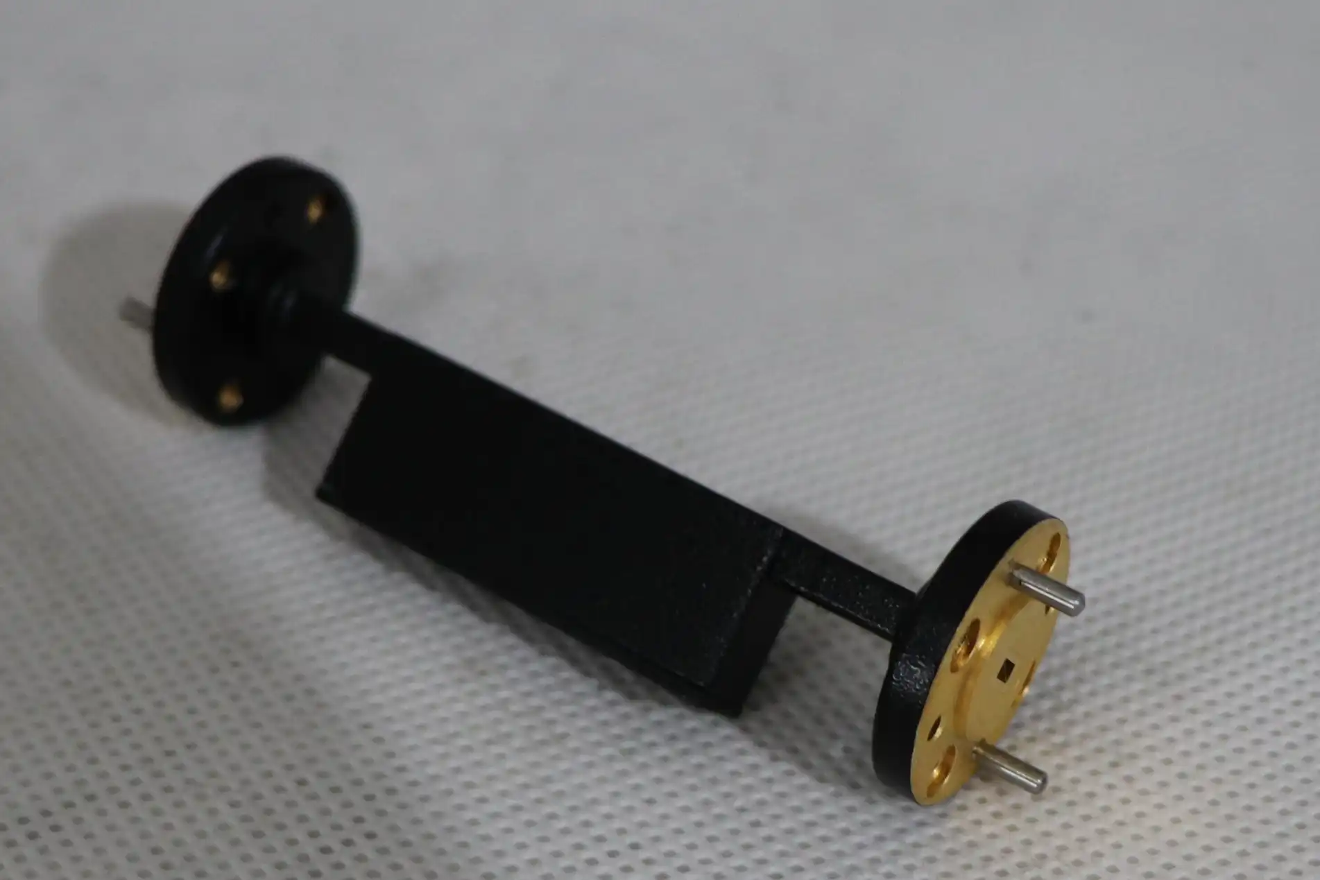
Variable models work best in automatic test equipment that has more than one reduction level to support a range of testing situations. Step attenuators let you change the level of reduction in discrete steps over switched networks. They combine the security of a set element with the ability to be adjusted. Pad attenuators are fixed devices that come in coaxial or microstrip form. They are often used to separate stages in chains of amplifiers.
Practical Applications Across Communication Infrastructures
Attenuators in 5G base stations keep the signal levels equal between the transmission outputs and antenna inputs. This stops intermodulation distortion, which lowers spectrum efficiency. Attenuators are used in ground station antennas of satellite communication systems to keep strong transmission signals from overloading low-noise amplifiers when the sky is clear. Attenuators are built into radar systems so that test configurations can simulate target returns at different ranges without the need for physical test objects.
Precision attenuators are used in antenna measurement facilities to set up known power levels for gain comparisons and calibrate reference channels. These parts are used by wireless backup networks to make the best use of link costs and make sure that signal-to-noise ratios are good without overloading receiver front ends. Attenuators help research labs make measures that can be used over and over again when they are characterising new RF parts or making sure that system designs work before they are put into production.
Comparing Microwave Fixed Attenuators: Key Considerations for Procurement
Functional Differences Between Attenuator Types
Knowing the differences between the different types of attenuators helps procurement teams choose the right parts. Microwave fixed attenuators offer constant reduction, making them ideal for long-term placements where signal levels are always the same. Variable attenuators can adapt to different situations, but they add complexity through mechanical adjustments or electrical control circuits, which could make them less reliable over time.
Pad attenuators are fixed-value devices that come in coaxial or planar transmission line formats and work very well for isolating stages. Step attenuators use switching matrices to choose between a set of fixed elements. This lets you make discrete changes to the reduction without an ongoing change. Fixed models are good for stable environments, variable versions are better for dynamic testing, step designs are better for precise adjustments, and pads are better for small integration.
Surface Mount Versus Connectorized Designs
Surface mount attenuators are attached directly to printed circuit boards using reflow soldering, which reduces their size and makes it possible for large numbers of them to be put together automatically. These designs work well for OEM uses where attenuators are built in permanently to bigger parts, like amplifier modules for cell phones or electronics in satellite transponders. Because of limited space, surface mount designs are preferred, but it can be hard to reach or replace these parts after they have been assembled.
Connectorized attenuators have coaxial or waveguide connections that make them easy to install and remove without tools during repair or testing. This gives procurement teams that work with test equipment makers or field service operations a lot of freedom, since technicians can quickly switch attenuation values without having to desolder. Power handling often prefers connectorized designs because their larger sizes make them better at getting rid of heat, which makes them good for testing transmitters where high levels of RF power occur.
Critical Performance Metrics for Datasheet Analysis
When purchasing managers look at attenuator specs, they should pay close attention to a number of factors. Specifications for accuracy show the range of limits used in production. Tighter values cost more but ensure consistent system performance. In receiver front ends, where sensitivity is affected by fractions of a decibel, noise figure contributions become very important. Good attenuators add very little noise above and beyond their thermal contribution, which is calculated from the attenuation value.
Power-handling specs include both average and peak scores, which show whether the device can work continuously or only for short periods of time. If you go beyond the stated attenuation, you'll experience unwanted losses due to connector transitions or resistor parasitic effects. Frequency flatness means that the attenuation is the same across the working band. Tougher requirements make sure that wideband systems have the least amount of gain change. Environmental scores for temperature, humidity, and vibration show if the product can be used in harsh conditions, which are popular in defense and aircraft uses.
Selecting the Best Microwave Fixed Attenuator for Communication Systems
Aligning Technical Requirements With Application Demands
Before making a purchase choice, microwave fixed attenuator specs must be matched with system needs. Frequency band considerations make sure the device works on all channels that are important. For example, 5G systems may use frequencies between 24 and 71 GHz, which means they need attenuators that are rated for millimeter-wave performance. Power handling must go above and beyond the highest expected signal levels with a sufficient safety margin. This is especially important when testing transmitters, where reflected power or loads that aren't matched could cause temporary overload conditions.
Material and building decisions are affected by the environment. For outdoor installs, you need housings that don't rust and connections that don't corrode. Designs that are temperature-stabilized keep their accuracy even when the weather changes. For military and aerospace uses, parts must meet MIL-STD standards for shock, vibration, and high altitude exposure. Customization is useful when standard catalogue items don't come in the right frequency range, attenuation value, or packaging format combinations.
5G and Emerging Technology Considerations
Choosing the right attenuator can be hard for next-generation wireless networks. To keep working, millimeter-wave bands above 24 GHz need parts with tight limits on size and low-loss dielectric materials. Massive MIMO antenna arrays in 5G base stations need a lot of attenuators for beamforming tuning, which increases the need for cheap options that don't skimp on quality.
For high-power uses like radar emitters, attenuators that can test kilowatt-level signals are needed. This calls for special waveguide or cable designs that have active cooling. To keep the ability to identify weak signals, low-noise uses in satellite ground stations aim for low passive intermodulation and minimal insertion loss. To find the best solutions among these competing needs, procurement teams and engineering groups need to work together closely.
Trusted Manufacturers and Quality Assurance
Buying from suppliers with a history of reliability lowers the risk of the purchase. Well-known companies keep a close eye on quality and test all important parameters one hundred percent of the time before sending their goods. ISO 9001 certification shows that a company is committed to using consistent production processes, and RoHS compliance makes sure that goods meet environmental rules so they can be sold all over the world. Suppliers who offer measurement reports that can be tracked back to national standards provide the paperwork that is needed for defence and aerospace uses.
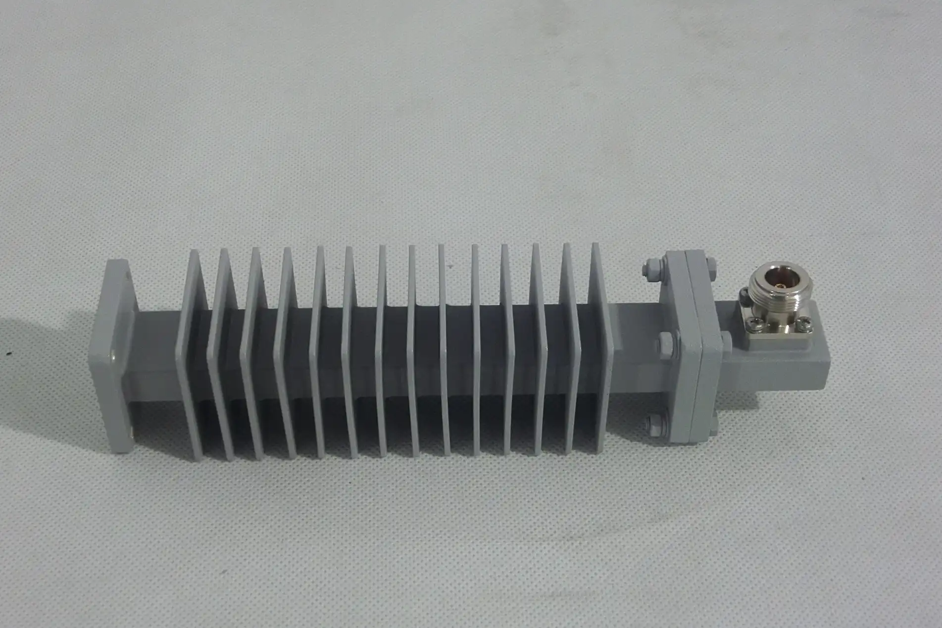
With more than 20 years of experience making microwave parts, Advanced Microwave Technologies Co., Ltd. is a great example of a company that puts quality first in its production. Because our lab can handle frequencies up to 110 GHz, we can thoroughly test how well attenuators work across all frequency ranges that have been specified. RoHS compliance and ISO 9001:2015 certification give buying teams peace of mind that the products will be made consistently and in an environmentally friendly way. This mix of technical know-how and good infrastructure serves mission-critical applications where a broken part could affect the safety or functionality of the system.
Optimizing Procurement and Supply Chain for Microwave Fixed Attenuators
Pricing Structures and Volume Advantages
The price of a microwave fixed attenuator depends on how complicated it is to make, how well it works, and how many you order. Because they are made in bulk, standard catalogue items with common frequencies and attenuation values tend to have lower unit costs. Custom designs, which cost more, can meet specific needs that off-the-shelf products can't, so they're worth the extra money for specialized uses. Significant cost savings can be achieved by buying in bulk, with price breaks common at 100, 500, and 1000-piece amounts.
Teams in charge of buying things should ask for formal quotes that include wait times, payment terms, and unit prices at appropriate volume levels. Setting up a framework with chosen sellers making it easier to place repeat orders and get better prices. Some manufacturers have consignment inventory programs where suppliers own the parts until they are used. This helps high-volume OEMs with their cash flow and makes sure that the parts are available right away.
Managing Lead Times and Logistics
Standard attenuator types usually ship within days or weeks from well-known companies that keep stock. For engineering approval, prototype builds, and production setup, custom designs take more time. Lead times of 8 to 12 weeks are normal for fully customized components. People who need delivery quickly may use rush services, but they will cost you more.
When shipping goods internationally, you need to think about logistics like customs paperwork, import taxes, and the best way to ship the goods. While air freight cuts down on transit time, it also costs more. On the other hand, ocean freight is cheaper for shipping large amounts of goods, but delivery windows are longer. Working with suppliers who know how to handle exports cuts down on clearance delays. Distributors who keep stock in their own regions make common models available locally, cutting down on lead times and making it easier to buy smaller amounts.
Custom Attenuator Ordering Process
For specialised uses, attenuators often need to be specially designed to meet specific needs. The process of customization starts with scientific talks about the frequency range, attenuation value, power handling, package style, and environmental needs. Manufacturers with a lot of experience can give design advice that improves performance while staying within budget and time limits.
Before committing to production, prototyping makes sure the design works by letting you check measurements and test how the system works together. At Advanced Microwave Technologies, our engineering team works closely with customers throughout this process and uses their years of experience in RF design to come up with the best solutions. Quick prototyping followed by flexible production makes sure that the change from development to release goes smoothly. After the product is delivered, technical support continues to help with installation and fixing problems as needed.
Conclusion
Microwave attenuators are an important part of many types of communication systems, from wireless networks on the ground to satellite links and defense radar sites. Procurement pros can choose the best parts by knowing the differences between fixed and changeable types, surface mount and connectorized packages, and different performance standards. To be successful at sourcing, you need to find a balance between technical needs and things like cost, supply chain logistics, and long-term availability. Partnering with experienced manufacturers that offer customisation options, quality certifications, and quick technical support is becoming more and more important for making sure projects succeed as communication systems move toward higher frequencies and more complex designs.
FAQ
1. What frequency ranges do microwave fixed attenuators typically cover?
Depending on their form and use, microwave attenuators can work with a wide range of frequencies. Basic models can work from DC to 18 GHz and can handle most commercial wireless and basic radar needs. For advanced 5G millimeter-wave technology and satellite transmission, mid-range devices go up to 40 to 50 GHz. Advanced attenuators can block signals up to 110 GHz, which helps with cutting-edge research, military tracking, and the development of new wireless standards. Advanced microwave technologies can still measure up to 110 GHz, which means that these difficult frequency bands can be fully characterized.
2. How should I interpret key datasheet parameters?
Some important specs are attenuation accuracy (the range of values from the nominal value), VSWR (the quality of matching the impedance), and power handling (the highest level of safety). Frequency flatness shows that the attenuation is the same across the operating band; tighter specifications work best for wideband uses. The temperature coefficient shows how stable behaviour is across a range of environmental factors. Our engineering team gives you detailed advice on how to interpret these parameters based on the needs of your specific application.
3. Are custom attenuator designs available?
Custom designs can be made to fit particular needs, such as non-standard attenuation values, specific frequency ranges, odd packaging forms, or higher environmental ratings. Through the whole process, from the first idea to production, we work with our customers and offer custom solutions when catalogue items don't work. Quick-turnaround development lets you test ideas before committing to full production, which lowers the risk of the project.
Partner With ADM for Your Microwave Fixed Attenuator Requirements
Advanced Microwave Technologies Co., Ltd. can help you with all of your Microwave Fixed Attenuator needs when you need precise RF components. We are a well-known maker and supplier that works with the defence, aerospace, satellite, and telecoms industries around the world. We have over 20 years of experience making things and can measure up to 110 GHz. Our ISO 9001:2015-certified facilities make designs that are exactly what you want. They also offer strict quality control and quick technical support. Email our team at craig@admicrowave.com to talk about your needs and find out how our attenuator options can help your communication system work better.
References
1. Pozar, David M. Microwave Engineering, Fourth Edition. Hoboken: John Wiley & Sons, 2012.
2. Kumar, Anand and Harish, A.R. RF and Microwave Engineering: Fundamentals of Wireless Communications. New Delhi: VSD Publishers, 2016.
3. Collin, Robert E. Foundations for Microwave Engineering, Second Edition. Piscataway: IEEE Press, 2001.
4. Sayre, Charles W. Complete Wireless Design, Second Edition. New York: McGraw-Hill Education, 2008.
5. Edwards, Terry and Steer, Michael. Foundations of Interconnect and Microstrip Design, Third Edition. Chichester: John Wiley & Sons, 2000.
6. Bahl, Inder J. Fundamentals of RF and Microwave Transistor Amplifiers. Hoboken: John Wiley & Sons, 2009.
YOU MAY LIKE
 VIEW MOREWaveguide E Bend
 VIEW MORERight Angle Waveguide To Coaxial Adapter
 VIEW MOREWaveguide Cable Assembly
 VIEW MOREDouble Ridge Twist Waveguide
 VIEW MOREWaveguide Flange Gasket
 VIEW MOREDigitally Controlled Phase Shifter
 VIEW MOREDual Linear Broadband Dual Circular Polarization Horn Antenna
 VIEW MORECassegrain Antenna
