Waveguide Assembly Explained: Components, Types, and Industrial Applications
A waveguide assembly is a special kind of high-frequency transmission line that is made to direct electromagnetic energy with little loss. It is usually made up of thin metal tubes made of copper, aluminum, or brass that guide waves by reflecting them inside the tube. In defense, satellite communications, and radar systems where stiff or flexible structures need to handle high power at microwave and millimeter-wave frequencies, these units are a must. For mission-critical systems requiring dependability and accuracy across bands from 0.5 GHz to 110 GHz and beyond, waveguide assemblies are the best option because they outperform coaxial lines in terms of power handling and signal integrity.
Understanding Waveguide Assembly: Components and Principles
Core Components of Waveguide Assemblies
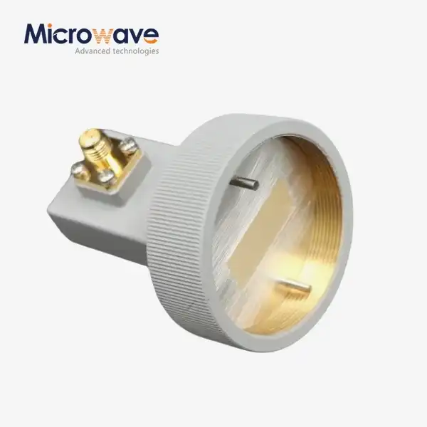
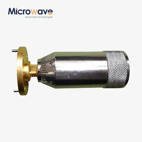
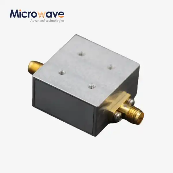
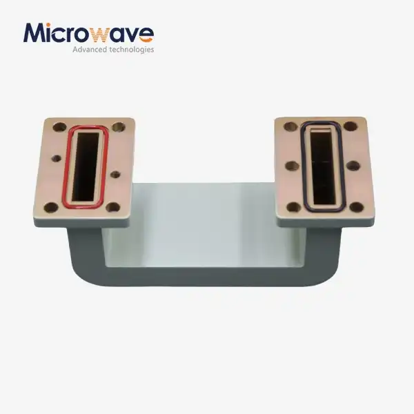
A standard waveguide assembly is made up of several carefully designed parts that work together. The base is the waveguide tube, which is a hollow electrical tunnel that keeps electromagnetic waves inside by reflecting them off the edges. As the connection point between parts, flanges need to be perfectly lined up to stop signal loss and keep the impedance constant. Connectors and fittings make it possible to switch between waveguides of different sizes or between waveguides and coaxial systems, especially when the setups are 90 degrees. Sealing parts keeps wetness out of internal surfaces, which can greatly lower performance by changing the dielectric qualities. Because even small flaws get louder at higher frequencies, each part has to fit within very strict limits.
Assembly Principles and Process
Paying close attention to technical detail is very important during the building process. Standardized flanges like UG, CPR, or UBR types are used to put waveguide pieces together. Precision jigs are used to line up the bolt holes and make sure the waveguide is flat. Gaskets or O-rings make covers that are RF-tight and keep the electricity flowing through joints. For the main TE10 mode to work, the internal surface needs to be carefully treated. Any burrs, rust, or contamination causes loss and VSWR spikes. When putting things together, techs often use dry nitrogen or inert gases to get rid of moisture. This is especially important for outdoor setups or systems that are under a lot of pressure. Mitered bends and twists are placed in a way that changes the direction of data or rotates polarization planes without losing or reflecting too much.

The Role of Precision Manufacturing
CNC cutting, electroforming, and precision extrusion are all modern methods used to make waveguides that are the right size for broad operation. The internal surface finish has a direct effect on insertion loss. Surfaces that are highly polished or silver-plated reduce resistance losses. Interlocking complex cores let flexible structures bend and twist while keeping their electrical properties. These bendable designs relieve mechanical stress in situations where hard pipes can't handle shaking, temperature changes, or mounting points for waveguide assemblies that aren't lined up correctly. To keep the impedance matching across the whole system, the change from hard to flexible designs needs to be carefully planned.
Types of Waveguide Assemblies and Their Industrial Applications
Classification by Geometry and Design
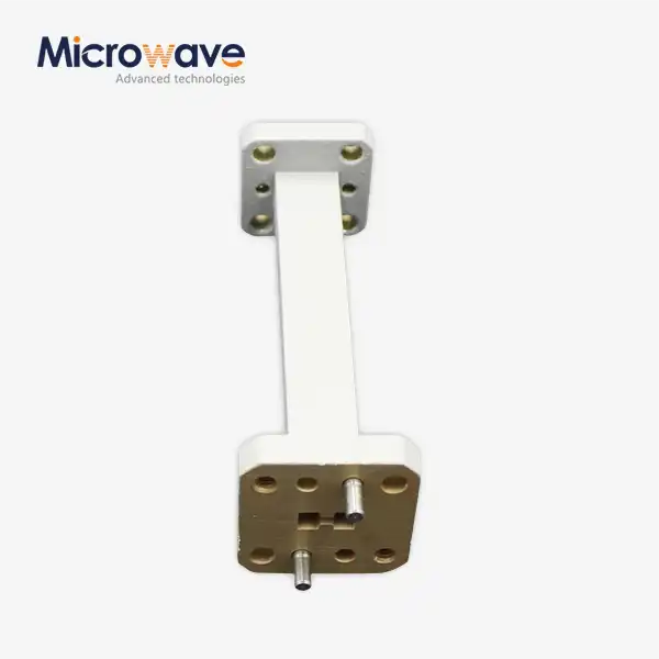
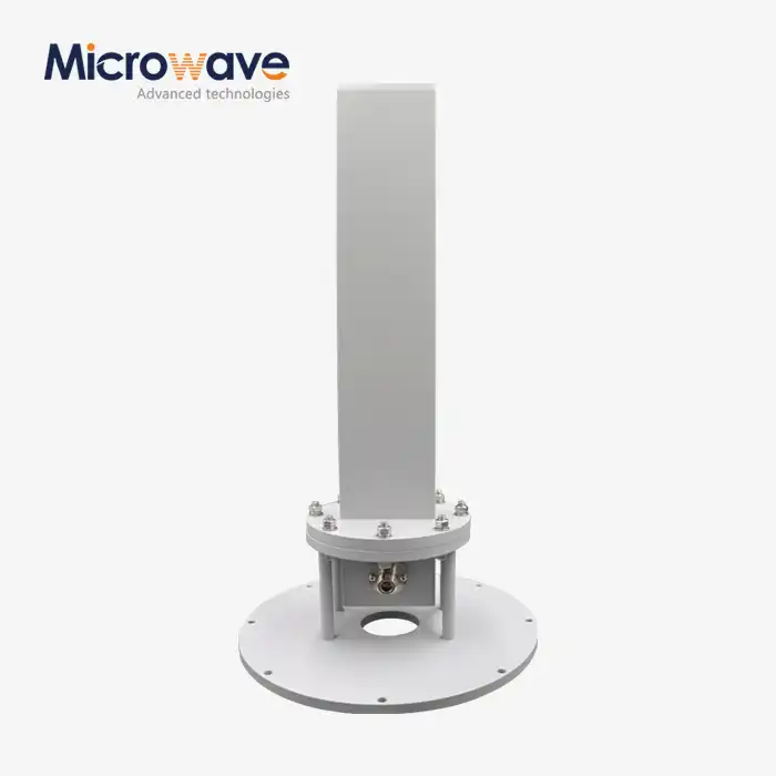
Rectangular waveguides are most common in microwave uses because they are easy to make and have known propagation properties. Common sizes, like WR-90 (which works in the X-band from 8.2 to 12.4 GHz), are defined around the world. This makes sure that products from different companies can work together. Circular waveguides can handle many modes and are useful in spinning joints and dual-polarization situations. Ridged waveguides have ridges inside them that lower the cutoff frequency. This lets them work with a wider bandwidth while taking up less room, which is very important for installations that are limited in area. Flexible waveguide assemblies, made up of twisted metal cores and protective jackets, are useful for integration problems where exact rigid alignment isn't possible. They provide the necessary shock absorption and vibration separation for mobile platforms.
Industry-Specific Applications
Ground stations for satellite communication use waveguide assemblies to connect high-power amplifiers to antenna feeds. These assemblies can handle kilowatts of send power in the Ku, K, and Ka bands without getting too hot or losing the signal. Low insertion loss (usually less than 0.5 dB per meter) keeps the signal strong even when equipment racks and antennas on the roof are far apart. Flexible waveguide assemblies are the most important part of radar systems, especially those that are used in the air or on the water. They connect gimbaled antenna arrays to fixed RF equipment. These assemblies keep the VSWR low even when the antennas move through their full azimuth and elevation ranges. This makes sure that the accuracy of target identification doesn't change. Defense electronic warfare systems need phase stability to be very precise. Any change in phase during mechanical flexure makes jamming less effective or direction finding less accurate. Vector network analyzers are connected to test and measurement equipment using waveguide assemblies. The mechanical flexibility lets engineers connect connections that aren't lined up right without putting too much stress on fragile test fixtures. The phase-stable construction ensures repeatable measurements that are important for defining 5G and new 6G parts. Weather radars that use millimeter-wave frequencies need waveguide assemblies that are made to work with temperatures ranging from -40°C to +85°C outside without losing their electrical performance. To give precise microwave power for deposition and etching processes, industrial uses in semiconductor manufacturing and plasma processing use waveguide assemblies.
Material and Construction Trade-offs
The choice of material strikes a balance between cost, weight, and electrical efficiency. Aluminum is a great conductor that is also light, making it perfect for use in the air where every gram counts. Copper is better at conducting electricity than other metals, so it is used for high-power ground systems. Brass makes it easier to machine parts with complicated shapes and samples. Surface techniques like silver plating lower resistive losses even more, especially above 40 GHz, where the skin layer is almost nothing. It takes a lot of thought to decide between rigid and flexible construction. Rigid assemblies offer the lowest loss and highest power handling, but they need to be installed perfectly aligned. On the other hand, flexible assemblies give up some performance for mechanical adaptability, waveguide assembly, and installation forgiveness.
Quality Standards and Troubleshooting in Waveguide Assembly
International Standards and Compliance
According to MIL-STD-3922, military-grade flexible waveguide assemblies must meet certain performance standards. These include being able to withstand millions of flex cycles, being resistant to the environment, and having the right electrical factors across all frequency bands. IEEE guidelines set the ways that VSWR, insertion loss, and power control can be tested. Having ISO 9001 approval shows that a company has quality management systems that are the same during the planning, production, and inspection processes. RoHS compliance gets rid of dangerous materials from assemblies so they meet environmental rules. Global purchasing teams give these approvals to sellers because they allow for tracking, consistency from batch to batch, and objective confirmation that goods meet recorded standards instead of depending only on what the vendor says.
Common Defects and Their Diagnosis
Misalignment of the flanges is one of the most common problems with assemblies. It shows up as high VSWR and possible RF leaks at joints. During installation, precision gauges check that the flanges are flat and aligned. Internal pollution from machine debris, oxidation, or water seepage gradually lowers performance; testing for leaks while pressurizing with dry gas shows seals that aren't working properly. When you bend flexible parts past the minimum bend radius, the core structure becomes forever deformed. This creates impedance discontinuities that can be seen as VSWR spikes in vector network analyzer sweeps. When the torque on flange bolts is too low, either the RF sealing isn't good enough, or the flanges bend, which causes stress concentrations. Phase instability during flexure is a sign of core degradation or poor fitting between convolutions.
Testing and Verification Methods
Full-band sweep testing with standardized vector network analyzers is done on every high-quality waveguide assembly. Test data plots show that insertion loss is within the limits set for the working band and return loss is better than 20 dB (VSWR below 1.22:1). In dynamic flex testing, phase stability is confirmed by regularly bending assemblies around mandrels that match the minimum bend radius while keeping an eye on phase variation. Premium assemblies keep phase variations within ±2 to 5 degrees. For outdoor setups, pressure testing proves the pneumatic integrity by putting units under certain amounts of pressure and watching for decay. This makes sure that water can't get in and damage the dielectric properties. High-power testing checks how well parts can get rid of heat without going over the temperature limits that would damage materials or solder joints. This is done under both continuous and high-power conditions.、

Choosing and Procuring Waveguide Assemblies: A Buyer's Guide
Aligning Specifications with Application Requirements
The first step in procurement is to define practical parameters. For example, the frequency range affects the size of the waveguide; smaller cross-sections can support higher frequencies but can't handle as much power. Power needs—both peak and average—determine wall width, material choice, and cooling issues. Material choices and protective layers are based on things like temperature changes, humidity, vibration patterns, and the possibility of chemical exposure. If stiff, semi-rigid, or fully flexible construction works best, it depends on mechanical factors like the amount of room available for routing, the bend radius needed, waveguide assembly, and the mounting configurations. Error budgets for the whole system must match the goals for VSWR, insertion loss, and phase stability.
Evaluating Supplier Capabilities
Suppliers you can trust show they can make things by having official licenses, records of how their test equipment was calibrated in line with national standards, and clear quality control processes. Production knowledge is important. Companies that have been delivering to demanding industries like aerospace and defense for decades have perfected processes that reduce errors. Technical support is what sets good providers apart from great partners. Experienced application engineers help with optimizing specifications, making changes to custom designs, and fixing installation problems. The global transportation system makes sure that delivery times are reliable and that projects can be sped up quickly when time is limited. When catalog goods can't meet specific needs, OEM service options like custom flange setups, non-standard lengths, and combined subassemblies give you options.
Custom Solutions and Lead Time Management
Standard catalog kits are ready to ship right away and have been shown to work reliably in common setups, but mission-specific needs often mean that they need to be customized. Custom waveguide assemblies are made for specific frequency bands, mounting connections that aren't standard, built-in transitions, or environmental protection needs. Prototyping services let you test your ideas before committing to large-scale production, which lowers the risk of new designs. Clear communication is needed for lead time management. Standard goods may ship within days, but complicated customs take weeks for proof of the design, tooling, production, and testing. Strategic buyers keep working ties with several qualified suppliers, combining the need to cut costs with the need for a reliable supply chain and high-quality expert support. Bulk procurement programs often let you get bulk discounts and make sure that the specs are the same for all setups that have more than one unit.
Conclusion
In the defense, military, satellite communications, and industrial fields, waveguide assemblies are essential technologies that make high-frequency electromagnetic systems possible. Procurement pros and system engineers can make decisions that balance performance, dependability, and cost by knowing their parts, types, quality standards, and the right way to choose them. Materials, manufacturing methods, and assembly methods are all changing all the time, which means that skills are getting better and new uses are opening up. To successfully use these complex parts, you need to choose qualified sources with a track record of success and follow strict installation and testing procedures that keep the design's performance throughout the product's lifetime.
FAQ
What tools are essential for waveguide assembly work?
For waveguide assembly work, what tools are necessary? Precision torque tools that are set up according to the manufacturer's instructions keep flange nuts from being too tight or too loose. Before mounting, flange alignment pins make sure that the flange is in the right place for movement. GO/NO-GO gauges check that flanges and contacts are the right size. Isopropyl alcohol and cleaning tools that don't leave behind lint keep surfaces clean. For testing, electrical performance can be checked with accurate vector network testers that cover the right frequency range and use precise calibration standards. During power tests, infrared thermal cameras find places that are very hot.
How do I detect defects early in waveguide assemblies?
Visual inspection finds clear mechanical damage like dings, kinks in flexible parts, or deformation of the joint. Swept VSWR readings across the whole operating band show impedance discontinuities caused by internal flaws, bad connections, or contamination; look for spikes or average values that are higher than what is expected. Testing phase stability under multiple flexure cycles finds flexible cores that are breaking down before they fail completely. When decay rates are watched during pressurization tests, problems with the seal's integrity are shown. When you compare recorded performance to data from the factory acceptance test right after receiving an assembly, you can be sure it came undamaged.
What distinguishes waveguide assemblies from coaxial assemblies?
Waveguide systems send electromagnetic energy through hollow metal tubes using TE or TM modes. Coaxial wires, on the other hand, use TEM mode to send energy between the center conductor and the outer shield. At frequencies above 18 GHz, waveguides have much lower insertion loss—often only a tenth of what coaxial lines have—and can handle a lot more power without getting too hot. Although waveguides need bigger cross-sections, they work better for permanent placements. For lower frequencies and portable uses, coaxial systems are flexible and easy to link. System makers pick based on performance needs, frequency, power, and available area.
Partner with ADM for High-Performance Waveguide Assembly Solutions
Advanced Microwave Technologies Co., Ltd. is ready to help you with your waveguide assembly needs. They have been making high-quality products for over 20 years for the defense, aerospace, satellite communications, and telecommunications industries around the world. Our ISO 9001, ISO 14001, and RoHS-certified factories make precise assemblies that are tested to 110 GHz in our cutting-edge 24-meter microwave darkroom. This makes sure that every part meets the strict requirements. Our experienced engineering team works closely with your purchasing and technical staff to create the best designs, whether you need standard stock items or fully personalized solutions with specific flanges, frequency ranges, or environmental protection. We keep our prices low by using efficient manufacturing methods, and we offer fast prototyping and short production plans to meet the needs of your project. Contact craig@admicrowave.com right away to talk to one of our technical experts about your waveguide assembly needs and find out why top companies around the world choose ADM as their chosen provider.
References
1. Pozar, David M. Microwave Engineering, 4th Edition. Hoboken: John Wiley & Sons, 2012.
2. Saad, Theodore S. Microwave Engineers' Handbook, Volume 1. Dedham: Artech House, 1971.
3. Collin, Robert E. Foundations for Microwave Engineering, 2nd Edition. New York: IEEE Press, 2001.
4. Marcuvitz, Nathan. Waveguide Handbook. London: Peter Peregrinus Ltd., 1986.
5. Institute of Electrical and Electronics Engineers. IEEE Standard for Precision Coaxial Connectors at RF, Microwave and Millimeter-wave Frequencies. IEEE Std 287-2007.
6. United States Department of Defense. MIL-DTL-3922: Waveguide, Flexible, Pressurizable. Defense Standardization Program, 2015.