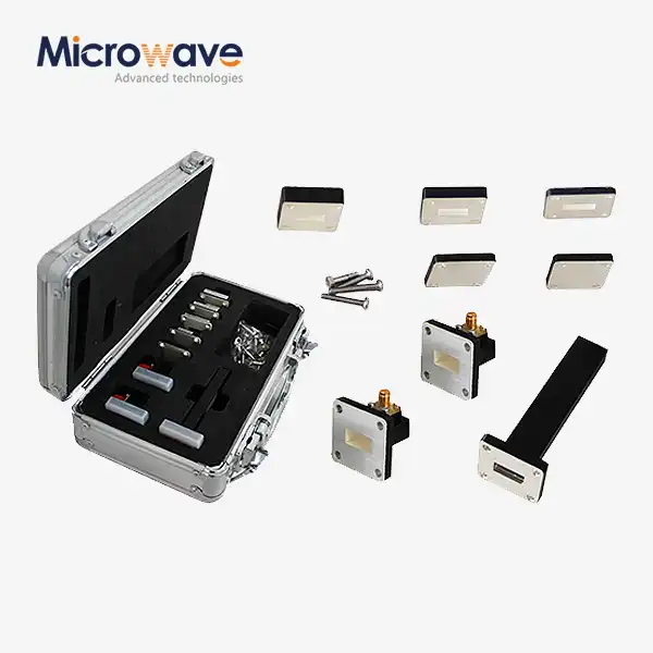
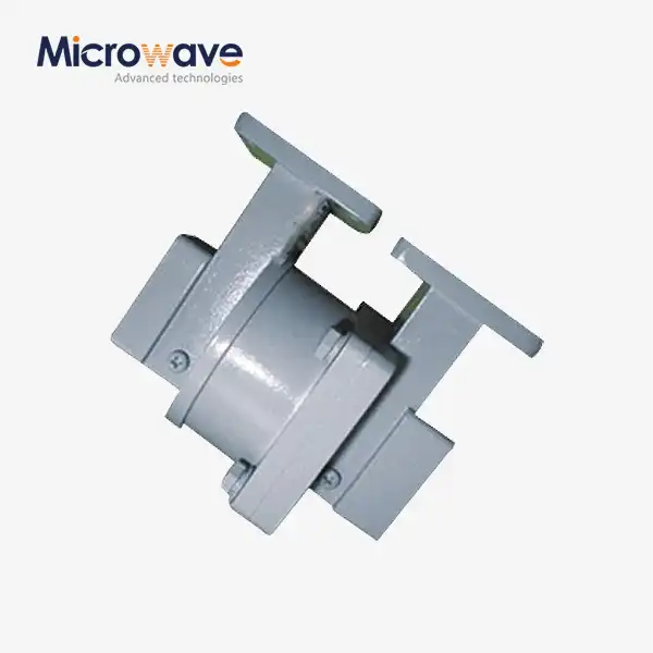
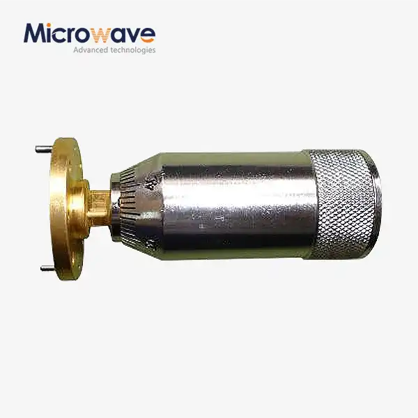
Broadband and compact rectangular waveguide twist by using rigid waveguide
Broadband and compact rectangular waveguide twists using rigid waveguide construction represent a critical evolution in RF transmission technology. These components enable precise polarization rotation—typically 90° or 180°—within constrained physical envelopes while maintaining exceptional electrical performance across wide Waveguide Twist frequency bands. By employing solid metallic construction rather than flexible alternatives, rigid waveguide twists deliver superior power handling, minimal insertion loss (often ≤0.1dB), and consistent mechanical stability essential for mission-critical aerospace, defense, and satellite communication applications where signal fidelity and long-term reliability cannot be compromised.
Understanding Broadband Rectangular Waveguide Twists
These specialized components work in RF signal chains as frequency-selective switches, sending energy based on spectrum content instead of time order. Unlike time-division duplexers, a high-quality Waveguide Twist utilizes natural frequency separation between transmit and receive bands to allow two-way communication at the same time, optimizing the throughput of modern satellite links.
The Role of Rigid Waveguide Construction
There are different parts of the Ku-band spectrum utilized in these assemblies. The lower part, from 10.7 GHz to 12.75 GHz, is mostly used for downlink reception in satellite communications. Two parallel filter paths meet at a common port on a device made for this range. The receive channel has bandpass settings centered on 11.7 GHz, and the transmit path aims for the uplink band 13.75–14.50 GHz. This design lets ground stations connect a single antenna feedhorn to separate high-power amplifiers and low-noise block downconverters without interfering with the signal.
Differentiating Broadband from Standard Designs
Measurement of insertion loss shows how much energy is lost through the device, which has a direct effect on how the link budget is calculated. Precision machining and low-loss dielectric materials, like PTFE composites or air-filled waveguide sections, are needed to get values below 0.5 dB. Isolation is the process of blocking out-of-band signals so that transmitter leakage doesn't reach sensitive receiver front-ends. Specifications above 70 dB keep high-power transmit signals from overloading these amplifiers, while typical power ratings reach 200W for ground-based applications.

Applications Across Critical Industries
Impedance mismatches can cause signal reflections that hurt power amplifiers and make the system less efficient. Technical teams should check the voltage standing wave ratio (VSWR) specs and twist the waveguide to aim for values lower than 1.3:1 across the operational bandwidth. Another worry is frequency drift caused by temperature changes, especially in outdoor installations exposed to temperature changes of -40°C to +85°C. Performance degradation is prevented by choosing temperature-compensated cavity designs or low-expansion metal alloys. Receiving bands in high-power systems are protected from passive intermodulation products by choosing silver-plated contacts.
Design Principles and Technical Specifications of Rigid Waveguide Twists
To design a high-performance Waveguide Twist, you have to optimize many electromagnetic parameters at the same time while keeping cost and ease of manufacture goals in mind. Modern design workflows combine full-wave electromagnetic simulation with automated optimization algorithms to explore parameter spaces with many dimensions.
Frequency Range Coverage and Mode Purity
To match the impedance across the 2 GHz bandwidth that most Ku-band components use, multi-section transformer networks are needed. Designers start by making basic filter topologies using Chebyshev or Butterworth polynomial synthesis. They are then improved by electromagnetic analysis that takes into account parasitic coupling and fringing fields. In waveguide designs, stepped impedance sections work well, while simulation case studies show that five-section Chebyshev transformers have a return loss of more than 20 dB across all operational bands.
Critical Electromagnetic Parameters
When the frequency is in the Ku-band range, conductor losses are the main way that energy is lost. This is because the skin effect concentrates current flow within a few micrometers of metal surfaces. Compared to copper, silver plating lowers surface resistivity by about 8%, which leads to improvements in high-volume signal paths. In coaxial systems, designers look for air-dielectric or low-loss PTFE formulations with tangent delta values below 0.0005. High-Q geometries in cavity resonator designs reduce loss even more by spreading out the electric field.
Mechanical Specifications and Tolerances
Putting transmission zeros in the right places in filter response functions is what makes cross-coupling suppression work. Manufacturers put attenuation poles at frequencies that match the passband of the other channel to create steep rejection skirts. When you use cross-coupled resonator configurations in advanced topologies, you get multiple transmission zeros, which is 15–20 dB better isolation than with regular ladder networks. Space decoupling between the transmit and receive filter sections adds to the isolation, especially in high-power applications where conducted paths could re-radiate interference.
Manufacturing Excellence and Quality Control
Practical installation guidelines stress the importance of correct grounding techniques to keep common-mode currents from weakening isolation. Low-impedance ground references are set up by mounting components directly to metal enclosures, and unwanted radiation is stopped by RF-tight covers. When you use conductive gaskets to seal an environment, the electromagnetic integrity stays the same even when the temperature and humidity change. Installation rules are included in procurement specifications to make sure that the performance in the field matches the data from the lab.
Comparing Broadband Rectangular Waveguide Twists with Alternatives
System architects choose which parts to use by weighing the pros and cons of performance, cost, and integration. Knowing the differences in how a Waveguide Twist and related technologies work, twist waveguide helps designers make the best decisions for single-frequency or dual-band applications.
Waveguide Twists versus Bends and Corners
For single-frequency applications where transmitting and receiving happen at different antenna ports, standalone bandpass filters are often used. However, this design doubles the amount of antenna infrastructure needed and makes mechanical parts more complicated. By combining RF interfaces, integrated components make systems lighter and less vulnerable to wind loading, which are important factors for mobile satellite terminals. There is a small cost increase compared to discrete filters, but this is balanced out by less installation work and better system reliability.
Comparison with Polarizers and Rotary Joints
Due to the effects of frequency scaling, high Ku-band systems that work in the 17.3–18.4 GHz downlink and 27.5–30.0 GHz uplink bands use different designs. The cross-sections of waveguides get smaller as the wavelength gets longer, which makes handling high power and manufacturing tolerances more difficult. Low Ku-band implementations have bigger physical sizes that make it easier to meet precision standards and control temperature. Market data from 2024 shows that WR-75 components cost an average of $800 to $1,500 per unit, while high Ku equivalents cost between $1,200 and $2,200.
Material Selection Impact
Additive manufacturing methods that use aluminum or titanium alloys promise lower production costs and faster prototype iterations compared to traditional CNC machining. Using three-dimensional printing makes it possible to make cavities with complex shapes that cannot be made with traditional subtractive methods, leading to better electromagnetic performance. Ceramics that have very low loss tangents and high dielectric constants help small designs work at high power densities. Prototype ceramic-loaded designs can reduce size by 40% while still working as well electrically as standard waveguide implementations.
Performance Benchmarks from Field Deployments
When satellite constellation operators put hundreds of spacecraft into low-Earth orbit, they want all of the subsystems to be as small and light as possible. Putting together multiple RF functions on a single substrate cuts down on interconnect losses and the number of parts needed. Active modules with built-in switching or amplification are possible with microwave monolithic integrated circuit technology. These changes are especially good for small satellites, where every gram of payload mass means more ways to make money or longer mission lifetimes.
Procurement Guide: How to Source and Buy Rigid Waveguide Twists
Strategic sourcing decisions for a Waveguide Twist weigh technical performance against business factors like lead times, customization, and supply chain dependability. Procurement professionals need organized ways to evaluate suppliers and ensure part specifications are correct.
Quality Standards and Certifications
Manufacturers who have been in business for a while and have ISO 9001 certification use systematic quality management processes to cut down on defects. RoHS compliance is checked for restrictive substance controls required for global markets. Looking at the RF test capabilities of a supplier helps figure out how well specifications are being met. Vector network analyzers that work between 0.01 and 40 GHz can fully characterize the component and show its harmonic response. It is important to see how production is controlled and how much can be made.

Customization Capabilities and OEM Services
Critical specification review looks at test conditions to see if insertion loss measurements take into account connector losses. For outdoor installations, temperature coefficients measure frequency stability across environmental conditions. Third-order intercept point specifications show if high-power applications are vulnerable to passive intermodulation. Asking for S-parameter files in Touchstone format allows system-level simulation, letting procurement teams check how well devices work in full RF chain models before making purchases.
Pricing Structures and Lead Times
Adjusting parameters can include changing the center frequency to work with regional spectrum allocations, the bandwidth for wideband systems, or the impedance to match non-standard interfaces. Customizing an interface includes changing the type of flange, the gender of the connector, and the mounting options. Depending on how complicated the mechanics are, the minimum order quantity for custom variants is usually between 25 and 50 units, and tooling costs range from $2,000 to $5,000.
Supplier Evaluation and Risk Mitigation
Standard items kept in stock make it possible to make prototypes quickly and get replacements in an emergency. For domestic orders, shipping is usually completed within 48 hours. With custom designs, engineering review cycles last for two to three weeks, and then assemblies are made over the course of six to eight weeks. 24–36 month warranties protect against manufacturing problems, and extended service agreements speed up replacement units to keep operations running as smoothly as possible. After-sales technical support helps with installation and system integration.
Troubleshooting and Maintenance for Waveguide Twists
Maximizing the lifespan of a Waveguide Twist requires proper separation of signals and maintaining mechanical integrity. Checking that all RF interfaces have tight connections stops signals from leaking through gaps or loose fasteners.
Identifying Signal Degradation Issues
The 10.7–12.75 GHz spectrum is used mostly for satellite downlink reception. Components designed for this range work best within these limits, with better insertion loss and isolation than broadband devices that try to cover multiple bands at once. If signal degradation is detected, technicians should verify the isolation at certain interference frequencies to ensure sensitive receivers are well protected.
Mechanical Wear and Installation Errors
By putting RF-absorbing materials around the mounting areas, cavity resonances that Waveguide Twist could transfer energy between ports are stopped. To keep long-term performance stable, connectors should be inspected regularly for corrosion or damage caused by mechanical stress. Not paying attention to how power needs to be handled by transmit path components can cause them to fail early or lose their performance.
Preventive Maintenance Best Practices
Environmental sealing protects the dielectric properties of the air inside by stopping moisture from getting in, which raises dielectric losses and weakens isolation. Asking for detailed mechanical drawings and interface specifications during the quotation phase avoids costly mistakes. Environmental sealing remains the most effective method for protecting dielectric properties in coastal or humid deployments.
Technical Support Engagement
ADM, or Advanced Microwave Technologies Co., Ltd., helps with satellite communication projects by providing well-thought-out solutions based on more than 20 years of experience. Our 24m microwave darkroom has advanced testing capabilities that go up to 110 GHz. Our engineering team works closely with procurement professionals and design engineers to make sure that the parts chosen are the best ones for your system.
Conclusion
Modern Ku-band satellite communication systems can't work without frequency-selective components, which make it possible to manage frequencies well in RF architectures that are getting more complicated. There are a lot of different selection criteria that technical buyers and procurement teams have to deal with. These include electrical performance, mechanical integration, supply chain reliability, and total cost of ownership. Understanding basic operating principles, design trade-offs, and the relative positioning of technologies helps people make smart decisions about which Waveguide Twist to use, aligning with both short-term project needs and long-term strategic plans. As satellite networks move toward higher throughput and global coverage models, companies that work with reliable suppliers offering both catalog products and custom engineering services will be better able to adapt.
FAQ
1. What frequency ranges do broadband rigid waveguide twists typically support?
The 10.7–12.75 GHz spectrum is the primary range for low Ku-band operation, mostly used for satellite downlink reception. While full Ku-band allocation goes up to 18 GHz, components designed for the lower range work best within these specific limits, offering superior insertion loss and isolation compared to generic broadband devices.
2. Can waveguide twists be customized for non-standard rotation angles?
To get the desired isolation, you need to do more than just choose the right components. Checking that all RF interfaces have tight mechanical connections stops signals from leaking through gaps. By putting RF-absorbing materials around the mounting areas of the device, cavity resonances that could transfer energy between ports are stopped, allowing for precise polarization alignment in complex feed networks.
3. How do I ensure compatibility with existing waveguide infrastructure?
Not paying attention to power needs or mechanical interface compatibility can cause delays in integration. Verification requires checking isolation at certain interference frequencies and asking for detailed mechanical drawings during the quotation phase. Environmental sealing is also necessary to protect the dielectric properties of the air inside the waveguide run.
Partner with ADM for Superior Waveguide Twist Solutions
Advanced Microwave Technologies Co., Ltd stands ready to support your polarization control requirements with precision-engineered waveguide twist solutions spanning 2.2GHz to 110GHz. Our two decades of manufacturing experience, ISO-certified quality systems, and 24-meter microwave darkroom testing capabilities ensure every component meets Waveguide Twist's exacting specifications. Whether you need catalog products for rapid deployment or customized OEM designs for unique system architectures, our engineering team provides comprehensive support from initial consultation through production and field deployment. As a trusted waveguide twist manufacturer serving defense contractors, satellite operators, and research institutions globally, we combine competitive pricing with flexible customization and dependable after-sales support. Contact craig@admicrowave.com today to discuss your specific requirements and receive detailed technical proposals backed by our commitment to reliability, performance, and customer success.
References
1. Marcuvitz, N. (1951). Waveguide Handbook. McGraw-Hill Book Company, New York.
2. Saad, T. S. (1971). "Broadband Twist Polarizer." IEEE Transactions on Microwave Theory and Techniques, vol. MTT-19, no. 9, pp. 792-794.
3. Balanis, C. A. (2012). Advanced Engineering Electromagnetics, 2nd Edition. John Wiley & Sons, Hoboken.
4. Microwave Engineering Handbook, Volume 1: Components and Subsystems (1992). Horizon House Publications, Norwood.
5. Jamnejad, V. and Hoppe, D. J. (2007). "Design of Compact Waveguide Twists for Deep Space Applications." IEEE Antennas and Propagation Magazine, vol. 49, no. 3, pp. 84-89.
6. Pozar, D. M. (2011). Microwave Engineering, 4th Edition. John Wiley & Sons, New York.