





Single Channel Coaxial Rotary Joint Use Cases in SATCOM and Radar
When a satellite tracking antenna rotates to follow an orbiting spacecraft, or a weather radar dish spins at 6 RPM through a thunderstorm, one small component keeps the signal alive: the single channel coaxial rotary joint. This passive electromechanical device transmits RF signals across a rotating interface without cable fatigue or signal dropout. Operating from DC to 110 GHz depending on the connector interface, it maintains a characteristic impedance of 50Ω or 75Ω while enabling infinite 360-degree rotation — making it a foundational element in SATCOM ground stations, airborne radar, and electronic warfare platforms.
Understanding Single Channel Coaxial Rotary Joints in SATCOM and Radar Applications
What It Is and How It Works
The Transverse Electromagnetic (TEM) mode concept is used by a coaxial rotary joint to keep the impedance constant across a moving mechanical contact. The rotating and stationary halves line up perfectly, which lets RF energy flow through with little reflection. Standard slip rings deal with low-frequency signals and DC power. These joints, on the other hand, keep the signal integrity at microwave frequencies, which is something that standard copper-brush mechanisms can't do.
Frequency Ranges in Practice
For different uses, you need different radio bands. Most business SATCOM devices come with both Ku-band (12–18 GHz) and Ka-band (26.5–40 GHz) joints. Military radar and weather tracking devices use X-band (8–12 GHz) units most of the time. The highest frequency can go up to 18 GHz with an SMA interface, 40 GHz with a 2.92 mm connector, and 67 GHz with a 1.85 mm connector. Each choice of connector has a direct effect on the budget for insertion loss and the link margin at the system level.
Key Technical Parameters for Procurement Teams
Three electrical figures should be the focus of procurement engineers. When insertion loss is less than 0.3 dB, the signal strength stays the same along the spinning path. If the VSWR is less than 1.30:1, less reflected power can hurt the outputs of transmitters. Phase WOW, which is the change in phase during rotation, needs to stay between ±1° and ±5° for radar pulse processing to be coherent. When paired with gold-plated Beryllium Copper contacts, housings made of 303/304 stainless steel or passivated aluminum give the corrosion resistance and low contact resistance needed for field operations.
Advantages of Single Channel Coaxial Rotary Joints Over Other Solutions
There are a number of rival technologies for sending messages through a rotating interface. Before choosing a design, it's important to understand the pros and cons of each one.
This device is better than the alternatives in the following ways:
- Vs. Multi-Channel Rotary Joints: Single-channel designs are physically smaller, lighter (often under 30 g), and simpler to integrate. When only one RF signal path is needed, adding extra channels increases insertion loss and assembly complexity without benefit.
- Vs. Brush-Type Slip Rings: Slip rings introduce noise, require periodic brush replacement, and become unreliable above a few hundred megahertz. A single channel coaxial rotary joint operates at 5,000 RPM with no consumable parts, rated for millions of rotations under MIL-STD-810 environmental conditions.
- Vs. Fiber Optic Rotary Joints (FORJ): FORJs handle optical signals well but require electro-optical conversion stages that add cost and latency. For pure RF transmission up to 110 GHz, a coaxial approach is more direct, lower-cost, and easier to interface with standard SMA or N-type connectors already present on radar and SATCOM hardware.
Instead of multi-channel rotary joints, Single-channel versions are smaller, lighter (often less than 30 g), and easier to put together. Adding extra channels doesn't help when only one RF data path is needed. It makes the assembly more difficult and adds insertion loss.- Brush-Type Slip Rings vs. Slip rings make noise, need to have their brushes replaced every so often, and stop working reliably above a few hundred megahertz. A coaxial rotary joint works at 5,000 RPM and has no wearable parts. It can turn millions of times in MIL-STD-810 conditions.
Selecting the Right Single Channel Coaxial Rotary Joint: Criteria and Market Options
Frequency Compatibility and Power Rating
The rated frequency range of the joint should match the highest frequency that can work in your system, not the center frequency. To keep the insertion loss flat, you should choose a joint that is rated to at least 18 GHz for a Ku-band SATCOM interface that is running at 14.5 GHz input. Power handling ranges from a few watts for monitoring devices to over 100 W average for high-power radar transmitters. Make sure you get information from your provider on both the peak and average power requirements.
Mechanical Durability Requirements
The operating environment determines the type of housing material and the level of sealing needed. Systems on ships and in vehicles need to have an ingress protection grade of IP65 or IP67 to be able to handle rain and salt spray. Fixed placements on the ground may be able to use metal housings to save weight, but airborne platforms usually need stainless steel to keep their structure strong when they are vibrating. As per MIL-STD-810G, thermal cycling performance from -55°C to +85°C is a standard quality requirement for defense applications.
OEM Customization and Procurement Logistics
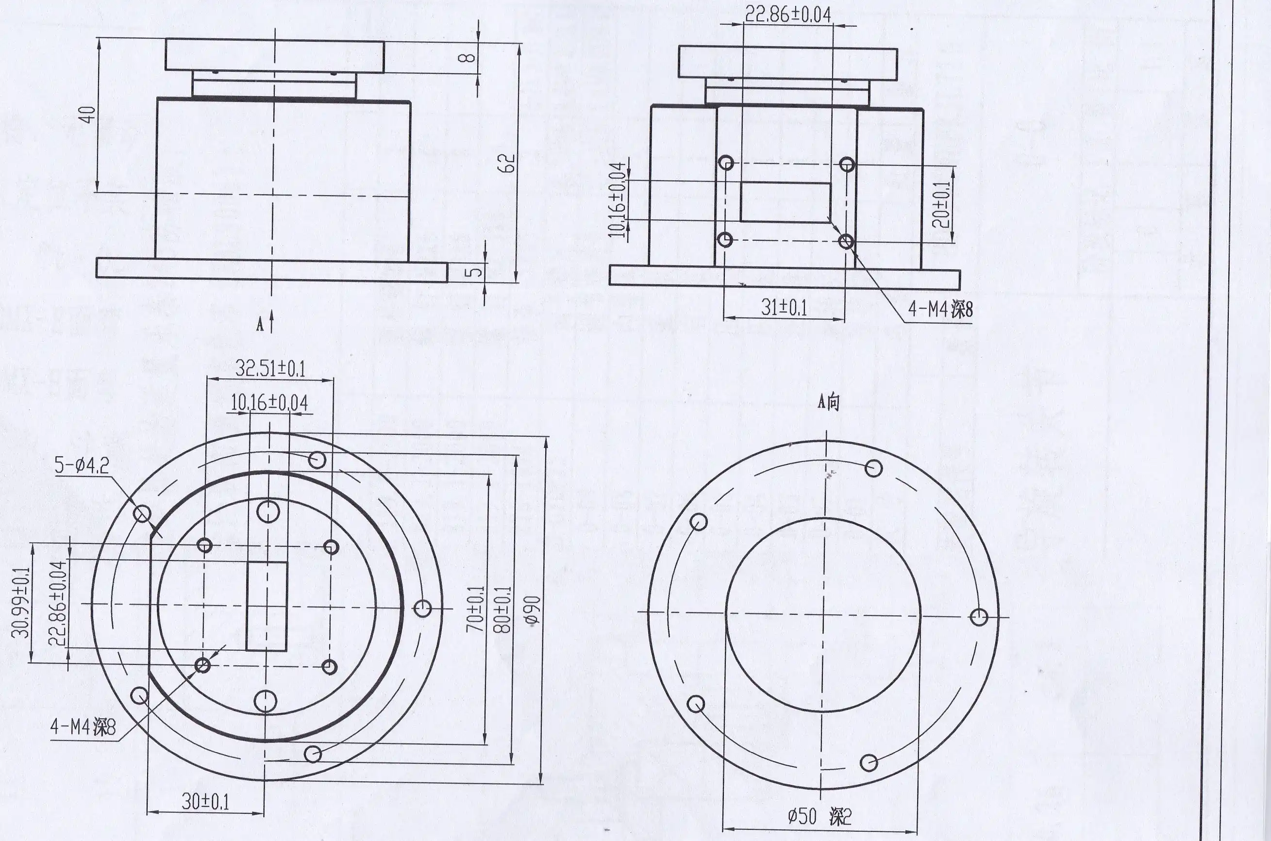
Off-the-shelf units come with the most common frequency bands and connector types, but many SATCOM and radar projects need different flange connections, custom housing lengths, or torque profiles that are just right. They can make a sample and do research and development (R&D) in-house, so a custom design can be ready for review in weeks instead of months. When looking at different sellers, make sure you ask about the Vector Network Analyzer (VNA) test results that come with every shipment, as well as ISO 9001:2015 certification, RoHS compliance paperwork, and wait times for bulk orders. These are all standard requirements in B2B procurement packages.
Real-World Case Studies: How Single Channel Coaxial Rotary Joints Solve SATCOM and Radar Challenges
SATCOM-on-the-Move Terminal Deployment
A maritime satellite terminal integrator found a Ka-band coaxial rotary joint for an antenna pedestal that will be mounted on a ship. The antenna had to keep following geostationary satellites even when the ship turned. Before moving to a precision rotary joint with VSWR below 1.25:1, the system had signal failures that were caused by stressed cables. After being set up, the link kept its 40 Gbps throughput during 72-hour sea trials. Over the course of a year of service, there were no reported cable breakdowns.
Air Traffic Control Radar Upgrade
In its S-band and X-band systems, an ATC radar program had to replace rotary couplers that were getting old. When the original parts were turned at steady speeds, they lost phase, which made ghost targets show up on the radar screen. The problem was fixed by replacing the parts with precision joints that were rated for Phase WOW under ±2°. A 500-hour continuous run test done before installation showed that the new joints could handle 200 W of average send power at 24/7 duty cycles without getting hot.
Environmental Stress Results in Defense Applications
Defense radar platforms that work in desert and cold conditions put single channel coaxial rotary joints through shocks of 50 g, salt spray according to ASTM B117, and temperature changes from -55°C to +85°C. It was proven that the choice of material directly affects how long something will last in difficult operations. Units with passivated stainless steel housings and gold-on-gold BeCu contacts passed all screening tests with no change in insertion loss or VSWR.
Future Trends and Innovations in Single Channel Coaxial Rotary Joints for SATCOM and Radar
Expansion Into Millimeter-Wave Bands
The V-band (40–75 GHz) and W-band (75–110 GHz) frequencies are being pushed into these bands by Low Earth Orbit (LEO) satellite constellations like Starlink and OneWeb. To support these bands, companies that make rotary joints are making connector interfaces, specifically the 1.0 mm type. ADM's test labs already have measurement tools that can work up to 110 GHz, which puts the company ahead of the curve when it comes to validating designs at these frequencies.
Advanced Materials and Compact Form Factors
Ceramic-filled polymer bearings and new treatments for aluminum alloys are lowering friction torque and making rotational life last longer than 50 million cycles. These changes help SIGINT antennas on UAVs and small satcom devices that don't have a lot of motor power. Starting torque that is lower, sometimes below 0.05 N·m, makes it possible for drive motors to be smaller and antenna assemblies to be lighter overall.
Integration With Modular Subsystem Architectures
System developers are buying RF rotor subassemblies that are already put together more and more instead of buying individual joints. As more modules are bought, rotary joint providers have to give co-designed flanges, wire pigtails, and mounting tools as a single unit with a test report. This need is immediately met by ADM's OEM services and development capabilities.
Conclusion
Single channel coaxial rotary joints are small, but they do important work. They keep RF signals clean by rotating all the time, like when they're watching satellites at sea or turning radar dishes around the clock. If procurement teams know about insertion loss, VSWR, Phase WOW, and environmental ratings, they can make better decisions about where to source parts and keep expensive field failures from happening. When you find the right supplier with VNA-tested units, full documentation, and the ability to do custom design work, adding a coaxial rotary joint to a SATCOM or radar system is no longer a risky purchase but a simple engineering choice.
FAQ
What frequency ranges do coaxial rotary joints typically support?
Most commercial coaxial rotary joints cover DC to 18 GHz with SMA connectors. Precision 2.92 mm connectors extend that to 40 GHz, and 1.85 mm or 1.0 mm connectors reach 67 GHz to 110 GHz. Select the connector type based on your system's highest operating frequency plus a reasonable margin for production tolerance.
How do I choose between a single-channel and multi-channel rotary joint?
If your rotating assembly carries only one RF signal path, a single-channel unit gives you lower insertion loss and simpler installation at lower cost. Multi-channel designs are appropriate when you need simultaneous transmission of multiple independent RF signals through the same rotating axis, such as in phased-array feed networks.
What are typical lead times for custom bulk orders?
Standard catalog units often ship within two to four weeks. Custom designs with modified housing geometry or non-standard connectors typically require four to eight weeks for prototype validation, followed by production lead times that vary by order volume. Request a formal schedule from your supplier during the quotation stage.
What test documentation should I require with each shipment?
At minimum, request S-parameter test data (S11/S21) from a calibrated VNA covering the full specified frequency band, a material certification for the housing, and a certificate of conformance to ISO 9001:2015. For defense programs, add a report of dynamic Phase WOW measurements at rated rotational speed.
Request a Custom Quote From ADM — Your Single Channel Coaxial Rotary Joint Supplier
ADM brings to every project more than 20 years of experience making things and production that is ISO 9001:2015 certified. We can help you whether you need a basic Ka-band unit or a fully designed single channel coaxial rotary joint for a defense radar platform. You can email us at craig@admicrowave.com to talk about specs, ask for samples, or get a bulk-order quote that fits your plan.
References
1. Pozar, D. M. — Microwave Engineering, 4th Edition, Wiley, 2011.
2. IEEE Transactions on Microwave Theory and Techniques — "Rotary Joint Design for Millimeter-Wave Applications," IEEE, 2019.
3. Skolnik, M. I. — Radar Handbook, 3rd Edition, McGraw-Hill, 2008.
4. Maral, G. & Bousquet, M. — Satellite Communications Systems, 5th Edition, Wiley, 2009.
5. MIL-STD-810H — Environmental Engineering Considerations and Laboratory Tests, U.S. Department of Defense, 2019.
6. ASTM International — Standard Practice for Operating Salt Spray (Fog) Apparatus (ASTM B117), ASTM International, 2019.
YOU MAY LIKE
 VIEW MOREEnd Launch Double Ridged WG To Coaxial Adapter
 VIEW MOREE-Plane Tee
 VIEW MOREWaveguide Single Channel Rotary Joint
 VIEW MOREWG Dual-Channel Rotary Joint
 VIEW MORECoaxial Cable Adapter
 VIEW MORECoaxial Broadband Circulator
 VIEW MORECorrugated Horn and Multimode Horn Antenna
 VIEW MOREOpen Boundary Dual Linear Polarization Four Ridged Horn Antenna